Control device of integrated ceiling air heating machine

A control device and warm-up technology, which is applied in the direction of air heaters, lighting and heating equipment, fluid heaters, etc., can solve the problems of short service life of heating switches, achieve improved safety, long service life, and avoid large current shocks Effect

Inactive Publication Date: 2009-10-14
JIASHAN XINHUYU ELECTRIC APPLIANCE TECH
View PDF0 Cites 4 Cited by
  • Summary
  • Abstract
  • Description
  • Claims
  • Application Information

AI Technical Summary

Problems solved by technology

[0005] In order to overcome the disadvantages of the existing integrated ceiling air heater with high current impact heating switch and short service life of the heating switch, the present invention provides an integrated ceiling air heater that can effectively avoid high current impact heating switch and improve the service life of the heating switch control device

Method used


Image

  • Control device of integrated ceiling air heating machine
  • Control device of integrated ceiling air heating machine
  • Control device of integrated ceiling air heating machine

Examples


Embodiment 1

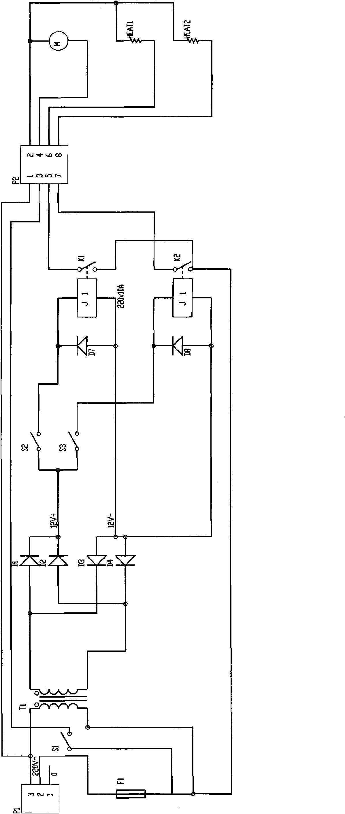
[0022] refer to figure 1 , a control device for an integrated ceiling air heater, including a motor switch S1 for controlling the fan motor and a heating switch for controlling the heater, the live wire of the commercial power is connected to one end of the fan motor M through the motor switch S1, so The other end of the fan motor M is connected to the neutral line of the commercial power, and the control device also includes a controlled relay, the controlled relay includes an electromagnetic coil and a contact switch, and the live wire of the commercial power is connected with the contact switch through the contact switch. One end of the heater is connected, and the other end of the heater is connected to the neutral line of the mains; the live line and the neutral line of the mains are respectively connected to the primary side of the step-down transformer T1, and the secondary side of the step-down transformer T1 is connected to the rectifier A circuit, the output end of t...

Embodiment 2

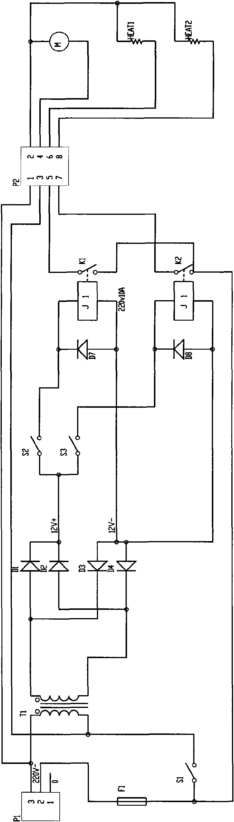
[0033] refer to figure 2 , the motor switch S1 of this embodiment is located between the mains live wire and the primary side of the step-down transformer T1.

[0034] Other circuit structures of this embodiment are the same as those of Embodiment 1.

[0035] The working process of this embodiment: first press the motor switch S1 to start the fan motor, and then press the first switch S2 or the second switch S3, if the first switch S2 or the second switch S3 is pressed first, the first fan motor cannot be started. Heater or second heater; it can effectively avoid the situation that the motor forgets to turn on when the air heater is turned on, and enhances safety.

Embodiment 3

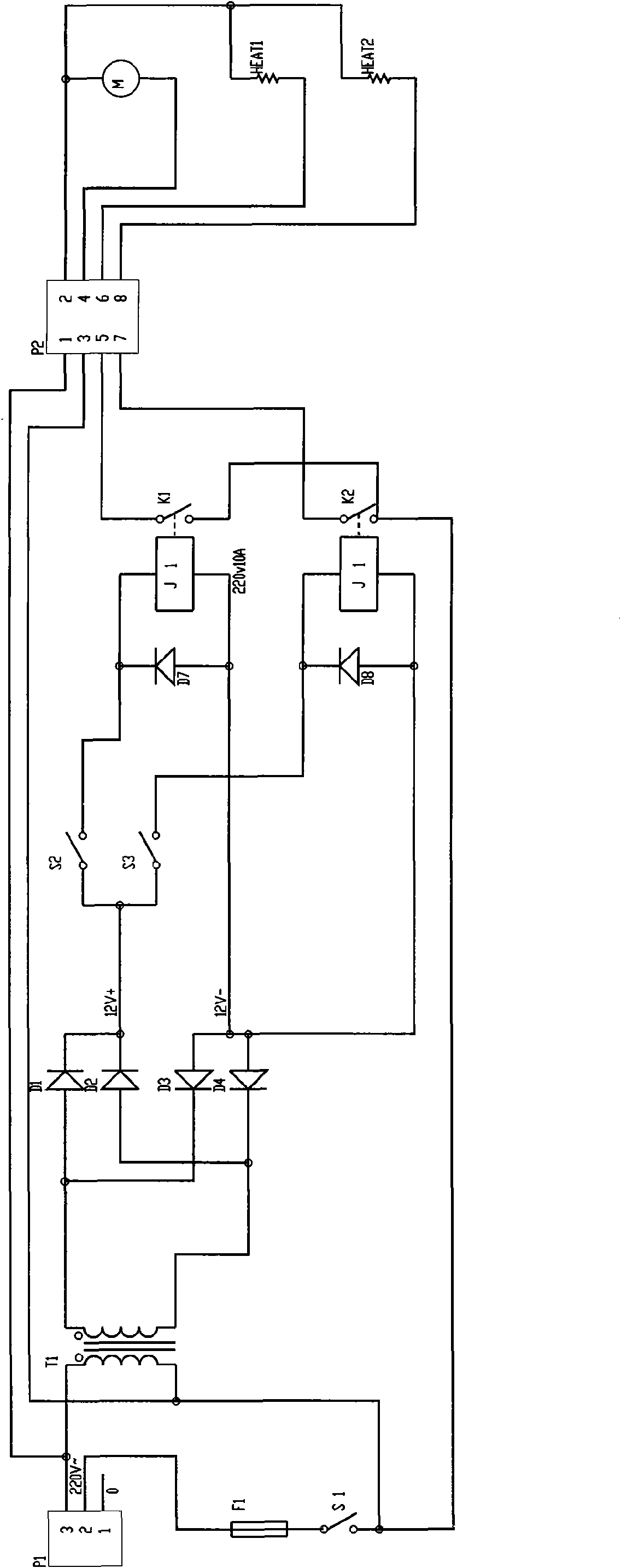
[0037] refer to image 3 In this embodiment, the motor switch S1 is connected in series with the contact switch K1 of the first relay or the contact switch K2 of the second relay.

[0038] Other structures and working processes of this embodiment are the same as those of Embodiment 2.


PUM


Abstract

The invention relates to a control device of an integrated ceiling air heating machine, which comprises a motor switch used for controlling a fan motor, and a heating switch used for controlling a heater. A commercial live wire is connected with one end of the fan motor by the motor switch; the other end of the fan motor is connected with a commercial zero line; the control device also comprises a controlled relay which comprises a magnet coil and a contact switch; the commercial live wire is connected with one end of the heater by the contact switch; the other end of the heater is connected with the commercial zero line; the commercial live wire and the commercial zero line are respectively connected with the primary side of a reducing transformer; the secondary side of the reducing transformer is connected with a rectifying circuit; and the output terminal of the rectifying circuit is connected with the magnet coil by the heating switch. The invention provides a control device of an integrated ceiling air heating machine, which can effectively prevent a heavy current from impacting the heating switch and prolong the service life of the heating switch.

Description

technical field [0001] The invention belongs to an air heater integrated with a suspended ceiling. Background technique [0002] The known fan heater with integrated ceiling includes a fan, a first heater and a second heater. The fan is driven by a motor. After the AC power is turned on, the motor is connected through a motor switch, and the first heater is connected through a first heating switch, and The second heater is connected through the second heating switch, and each function is realized by pressing the motor switch, the first heating switch and the second heating switch respectively during use. [0003] Because the power of the first heater and the second heater in the air heater is very large, therefore, for the first heating switch and the second heating switch, a large current will be generated when the heating switch is closed, and the large current has a great impact on The heating switch forms an impact. After being used for many times, the switch will be br...

Claims


Application Information

Patent Timeline
IPC IPC(8): F24H9/20F24H3/02
Inventor 杨和生
Owner JIASHAN XINHUYU ELECTRIC APPLIANCE TECH
Why Eureka
Try Eureka