Switching mechanism

A locking mechanism, switch shaft technology, applied in the direction of electric switch, contact drive mechanism, power device inside the switch, etc., can solve the problems of arc formation and disconnection, and achieve the effect of simple structure

Active Publication Date: 2009-10-14
K & N SCHALTERENTWICKLUNGSGES
View PDF4 Cites 13 Cited by
  • Summary
  • Abstract
  • Description
  • Claims
  • Application Information

AI Technical Summary

Problems solved by technology

[0005] The proven disadvantage is that when the locking mechanism of this type of electrical switch is closed, that is, when the contact is closed, after crossing the dead point of the spring, the user may feel the reaction of the spring force, and the closed contact Changing handles rapidly to and from open contacts may cause arcing
[0007]When opening, that is, when the contacts are open, these known electrical switch latching mechanisms still have a disadvantage: when the contacts are welded due to a short circuit , these locking mechanisms still allow for almost full handle turning
But practice has shown that in the above example of contact welding due to a short circuit, opening is possible despite the mechanical safety measures, since the handle is only locked shortly before the opening position

Method used


Image

  • Switching mechanism
  • Switching mechanism
  • Switching mechanism

Examples


Embodiment Construction

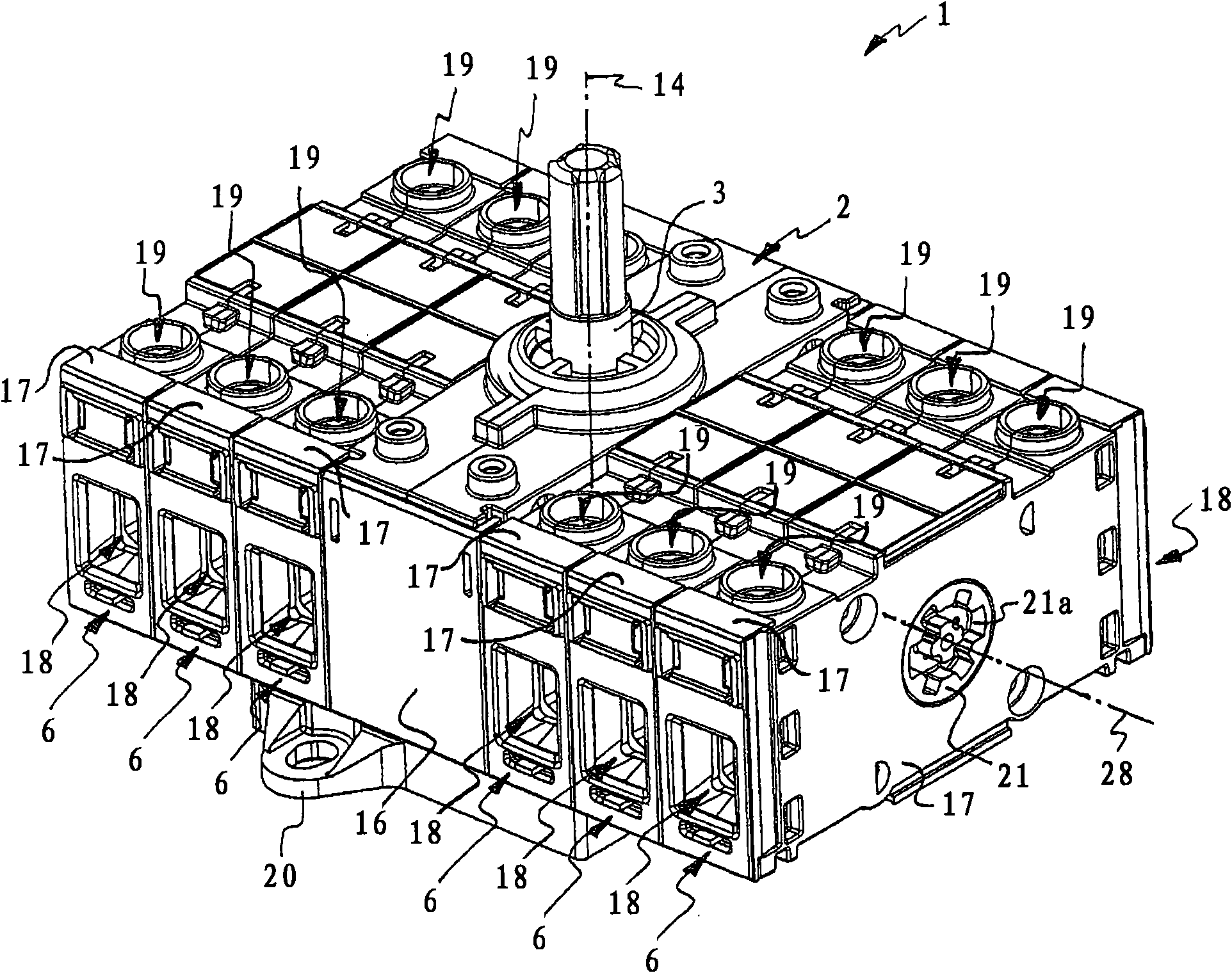
[0049] figure 1 An electrical switch locking mechanism 1 is shown, which has a main locking mechanism 2 in which a drive shaft 3 is rotatably mounted in a substantially cuboid-shaped housing 16 . Any number of switch modules 6 are arranged on both sides of the main locking mechanism 2 . In this embodiment, there are three switch modules 6 on the left side and the right side of the main locking mechanism 2 respectively, which have a substantially rectangular parallelepiped housing 17, and these modules are respectively coupled with adjacent switch modules 6 through coupling devices 21 .

[0050] like Figure 8 As shown in the vertical sectional view of such a switch module 6, in each housing 17 of the switch module 6 there is provided a substantially cylindrical contact carrier 5 which is rotatably supported about an axis of rotation 28. Two first contact sections 24 made of an electrically conductive material are arranged in the contact carrier 5 , for example made of plast...


PUM


Abstract

The present invention discloses a switching mechanism (1), which has a main arresting mechanism (2) including a drive shaft (3) and a transmission output device (4) that coupled on the drive shaft; the transmission output device (4) couples with a movable contact supporting (5) in a mechanical way, so as to make an electric contact closed or disconnected because of movement of the contact supporting (5) when operating the drive shaft (3). In order to improve operational reliability of the switching mechanism (1), according to the present invention, an auxiliary arresting mechanism (7) including an actuating unit (8) with a switching shaft unit (9) coupled with the actuating unit (8) is provided; a switch shaft device is coupled with a drive shaft (3) of a main arresting mechanism (2) overa combiner unit (10); a transmission device is provided with at least one tow retainer (11) that cooperates with towing elements (12a, 12b) of the units (8, 9) to transfer a movement of the actuatingunit; the combiner unit (10) is pre-stressed against the movement using a spring element (13) as a over-center spring, in order to press the unit (10) in initial or end position and to allow movementof the shaft unit, and the switching shaft unit (9) is capable of moving dependent with manual operation of the actuating unit (8).

Description

technical field [0001] The invention relates to a locking mechanism for an electrical switch according to the features stated in the preamble of claim 1, with a main locking mechanism comprising a drive shaft and a drive output coupled to the drive shaft , the transmission output device is mechanically coupled with the movable contact bracket, so that when the drive shaft is operated, an electrical contact is closed or opened due to the movement of the contact bracket. Background technique [0002] Such switch latching mechanisms are already known and described in relevant standards, eg EN 60947-1:2004 (IEV 441-14-10, IEV 441-14-12). These latching mechanisms can be used in particular for switch-disconnectors, load-break switches or DC switches. [0003] The drive shaft of the primary latch mechanism is usually directly connected to a handle that allows the user to actuate the drive shaft, which is then directly coupled to a transmission output that is in turn coupled to on...

Claims


Application Information

Patent Timeline
Patent Type & Authority Applications(China)
IPC IPC(8): H01H3/32
CPCH01H5/06H01H19/26H01H3/30H01H19/24H01H1/2041H01H19/64H01H3/001
Inventor C·施耐德
Owner K & N SCHALTERENTWICKLUNGSGES
Why Eureka
Try Eureka