Manufacture of electric motor component

一种定子、定子极的技术,应用在电动组件、电气元件、磁路静止零部件等方向,能够解决未最大化可用安装空间等问题

Active Publication Date: 2009-10-14
BURGESS NORTON MFG
View PDF1 Cites 4 Cited by
  • Summary
  • Abstract
  • Description
  • Claims
  • Application Information

AI Technical Summary

Problems solved by technology

[0006] Symmetrically shaped cylindrical motors of the prior art do not maximize the usable installation space available at the installation location

Method used


Image

  • Manufacture of electric motor component
  • Manufacture of electric motor component
  • Manufacture of electric motor component

Examples


Embodiment Construction

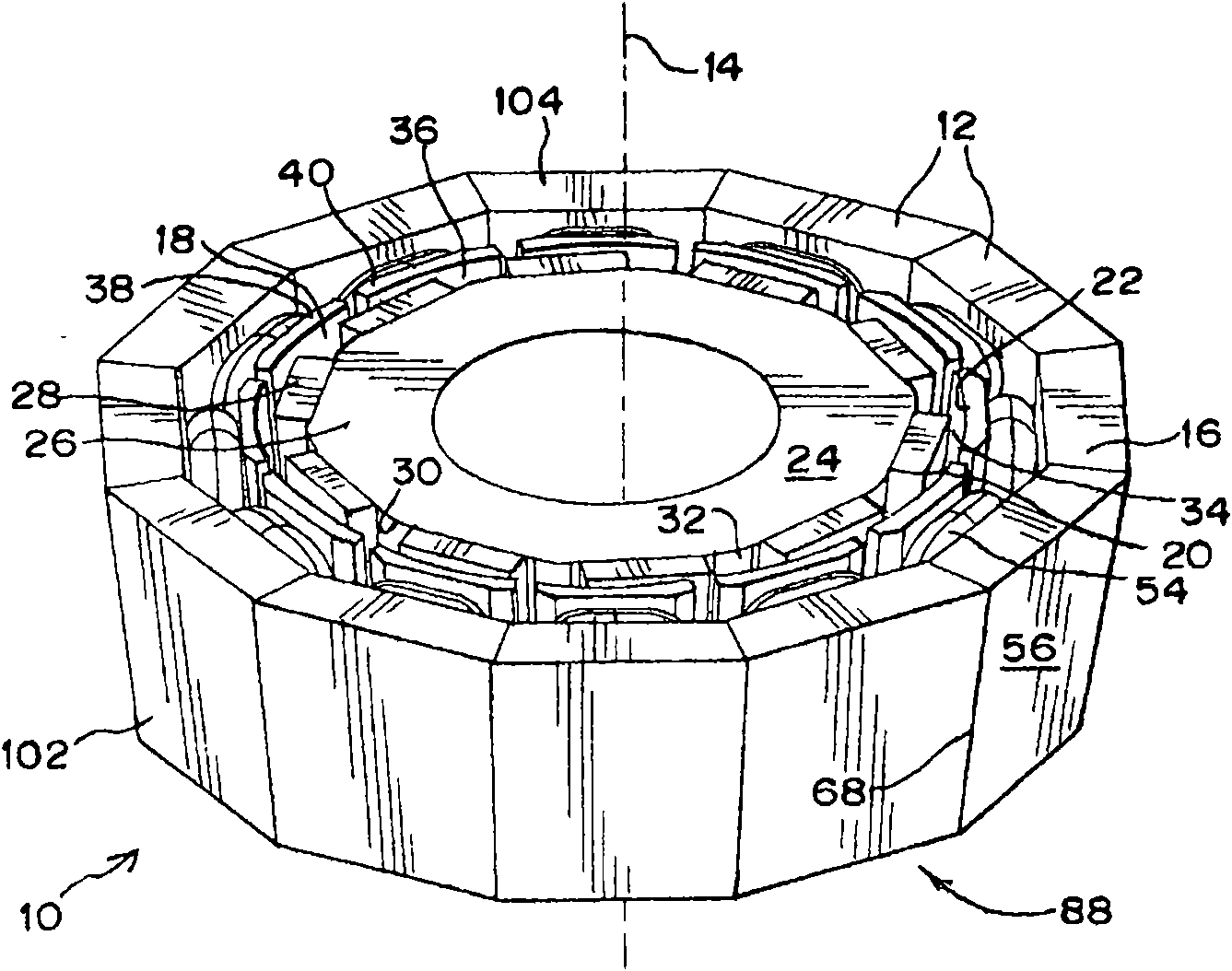
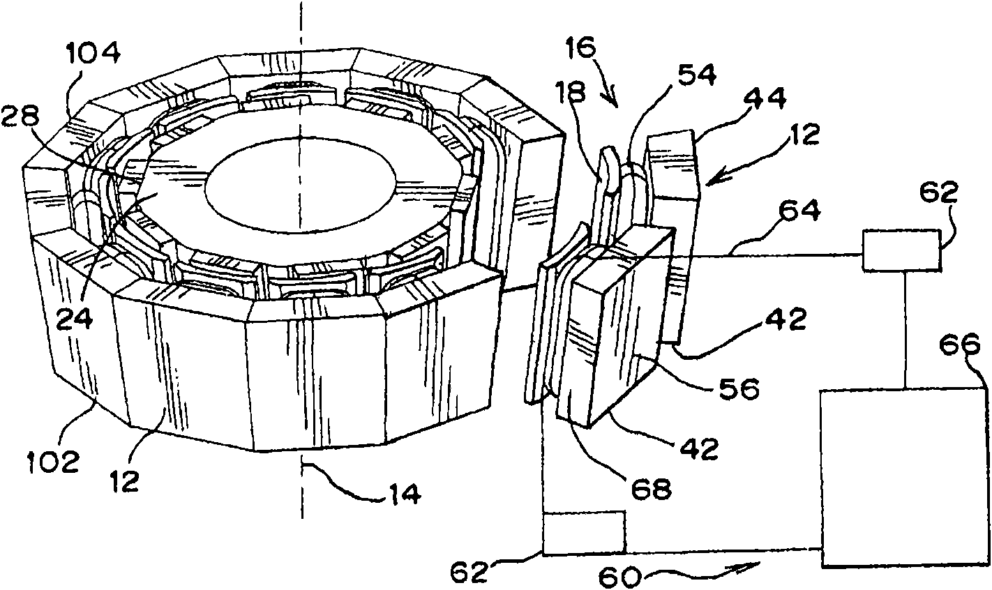
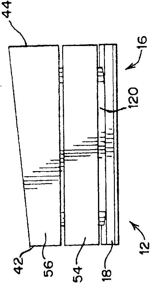
[0024] refer to figure 1 , the conical stator 10 includes a plurality of stator poles 12 assembled circumferentially about a stator axis 14 . Each pole 12 includes modular molded teeth 16 . The tooth 16 includes a stator face 18 and a tooth body 120 ( Figure 3B ). The stator face 18 has a generally rectangular shape inclined at an axial angle to define a conical inner surface 20 which defines a rotor volume 22 . The rotor 24 is rotatably mounted in the rotor space. The rotor 24 is axially aligned along the axis 14 of the stator and held in place for rotation in the rotor space by bearings or the like (not shown). The rotor includes a core 26 having a plurality of magnets 28 arranged along an outer perimeter 30 . The magnets 28 are isolated from each other by a divider 32 . Each magnet 28 defines a pole on rotor 24 . Outer perimeter 30 is precisely machined to maintain a predetermined clearance 34 between rotor 24 and stator 10 .

[0025] The stator 10 partially surrou...


PUM


Abstract

The modular conical stator pole provides an improved conical stator assembly on electrical machines. The improved conical stator pole assembly comprises a plurality of stator poles, each pole comprises an assembly having a coil secured on a soft magnetic composites (SMC) stator pole tooth by inserting a winding support through the open core of the coil and attaching a back iron and a stator face to either end of the winding support. Each stator pole has a parallelogram shaped cross section for forming a conical shaped rotor space when the stator poles are assembled, the back irons are bore against each other to space the coils apart and form a conical shaped outside profile of the stator pole assembly. The conical stator has a small end and a big end. The tooth comprises a winding supportintegrally molded with the back iron the face.

Description

technical field [0001] This invention relates to electric machines and more particularly to the design and manufacture of conical stator assemblies. Background technique [0002] Electric motors and generators have a stationary element called a stator and a moving or rotating element called a rotor. The interaction between the stator and the rotor is caused by the interaction of the magnetic fields generated by the stator or the rotor. Such magnetic fields are typically generated or induced by current flow in windings placed on the stator or rotor, or both. The force exerted on the rotor is a function of the interaction of the stator and rotor magnetic fields and the moment arm of the rotor calculated by the radial displacement of the rotor's magnetic field relative to the axis of the rotor. Such stator windings generally comprise a plurality of coils wound around a winding support. Winding supports are generally composed of soft magnetic materials traditionally manufactu...

Claims


Application Information

Patent Timeline
Patent Type & Authority Applications(China)
IPC IPC(8): H02K1/14H02K3/18H02K1/02H02K15/02H02K15/095
CPCH02K15/022H02K1/148Y10T29/49009
Inventor D·法尼亚
Owner BURGESS NORTON MFG
Why Eureka
Try Eureka