Wireless ic device

A wireless and device technology, applied in the field of wireless IC devices, can solve the problem of large size of wireless tags and achieve the effect of miniaturization

Active Publication Date: 2009-10-14
MURATA MFG CO LTD
View PDF1 Cites 7 Cited by
  • Summary
  • Abstract
  • Description
  • Claims
  • Application Information

AI Technical Summary

Problems solved by technology

In addition, it is necessary to arrange matching parts with large dedicated areas for each pair of main anten

Method used


Image

  • Wireless ic device
  • Wireless ic device
  • Wireless ic device

Examples


no. 1 example

[0045] (first embodiment, refer to Figure 1 ~ Figure 4 )

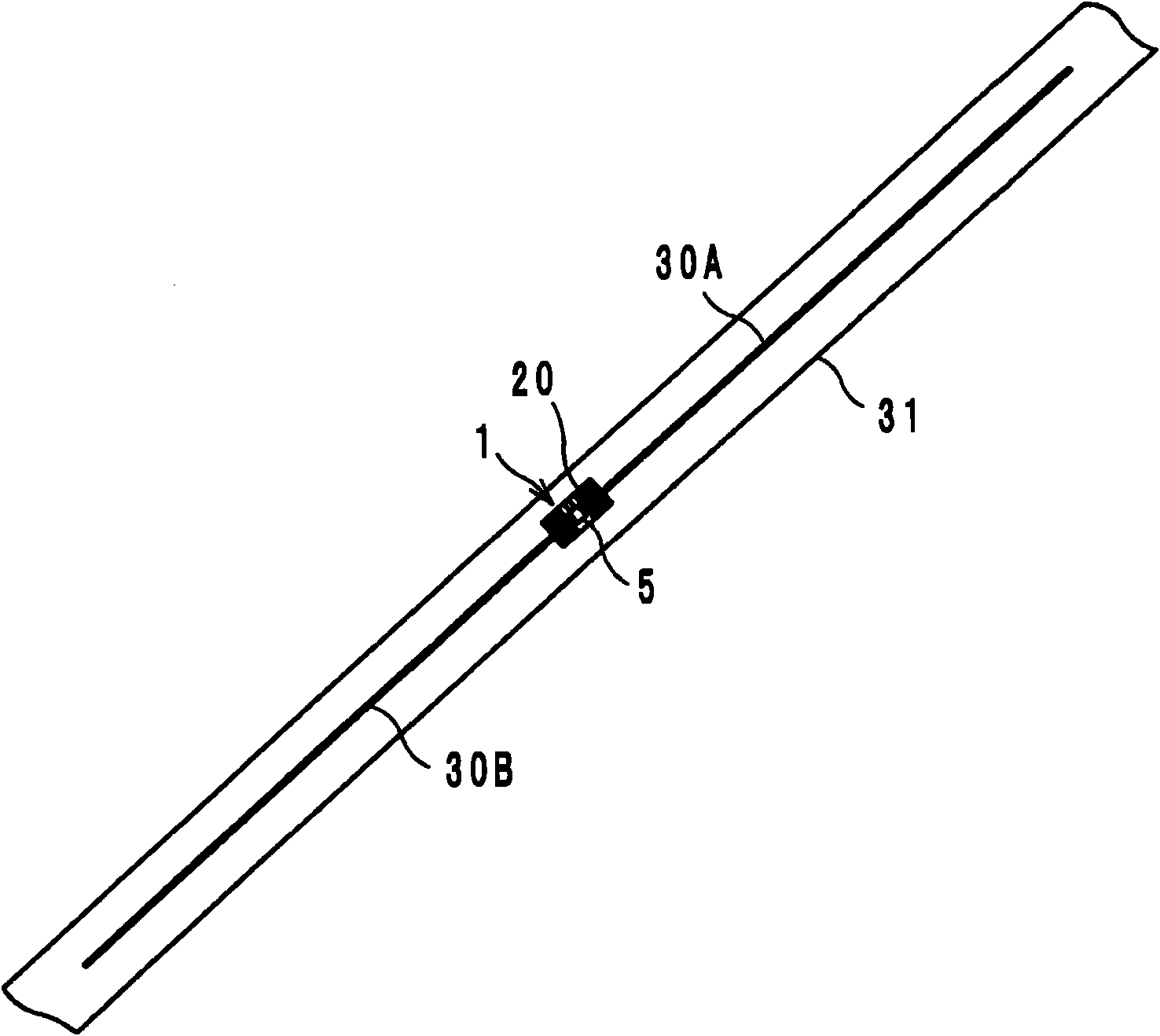
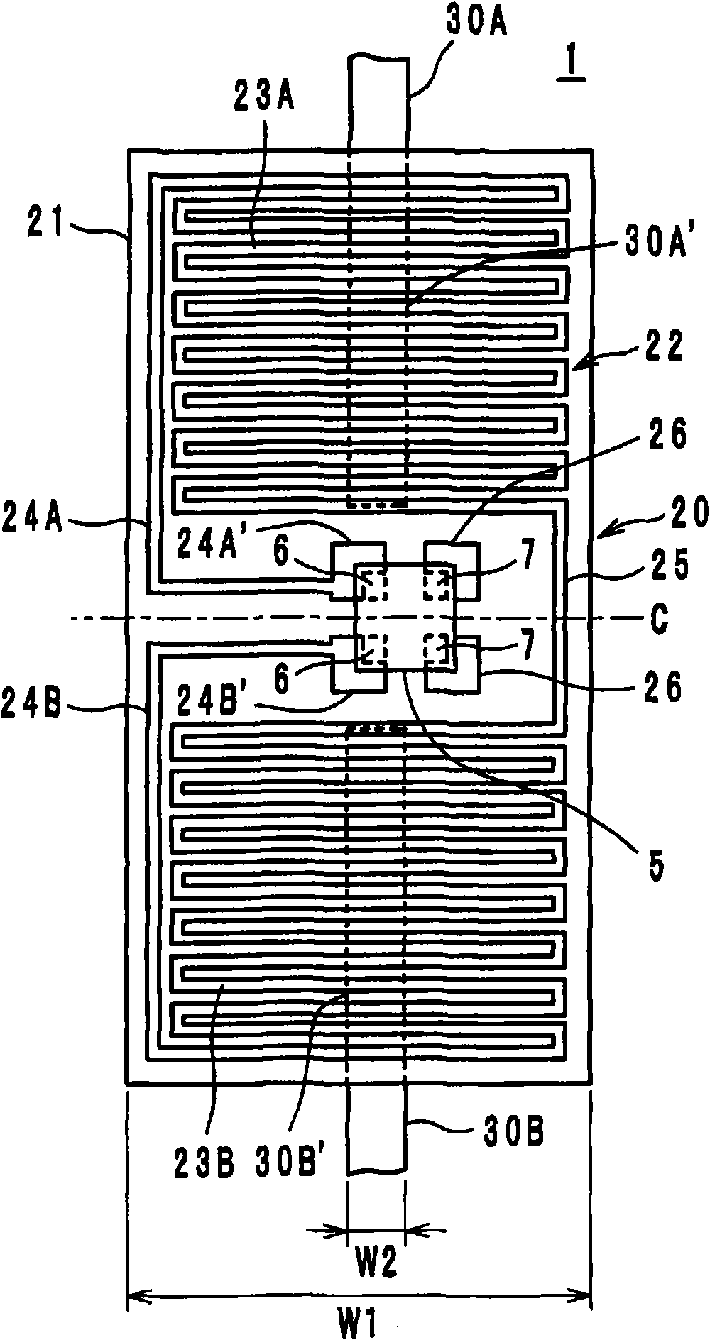
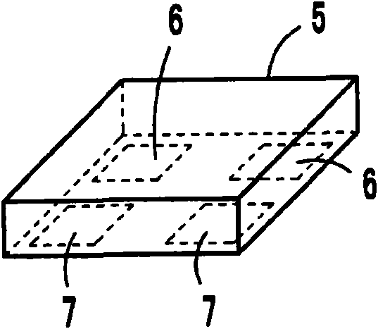
[0046] figure 1 , figure 2 and image 3 A first embodiment of the wireless IC device is shown. This wireless IC device is composed of: a wireless IC chip 5 that processes transmission and reception signals of a predetermined frequency; The second coupling portion 23B includes an inductance element composed of linear electrodes 24A and 24B; and a first radiation plate 30A and a second radiation plate 30B formed on a substrate 31 made of PET film and functioning as an antenna. The wireless IC chip 5 is mounted on the power supply circuit board 20, and the electromagnetic coupling module 1 is constituted by both.

[0047] The first and second radiating plates 30A and 30B are formed by linearly placing a metal material on the flexible film substrate 31 , and function as so-called dipole antennas. In addition, one end of the first and second radiation plates 30A, 30B has first and second mounting portions 30A', 30B'...

no. 2 example

[0061] (Second embodiment, refer to Figure 5 )

[0062] Figure 5 A wireless IC device of the second embodiment is shown. In this wireless IC device, the first coupling portion 23A and the second coupling portion 23B of the power supply circuit 22 provided on the power supply circuit board 20 are formed by meandering linear electrodes 24A, 24B, and the linear electrodes 24A, 24B are partially divided into two parts. Fork (fork point reference numeral 27). Other configurations are the same as those of the first embodiment described above.

[0063] The effect of this second embodiment is the same as that of the first embodiment, especially because the linear electrodes 24A, 24B are branched, so because the lengths of the branched parts are different, the first coupling part 23A and the second coupling part 23B can be used. By obtaining a plurality of different resonant frequencies, the peak frequencies of the gains of the first and second radiating plates 30A and 30B functi...

no. 3 example

[0064] (the third embodiment, refer to Image 6 )

[0065] Image 6 A wireless IC device of a third embodiment is shown. In this wireless IC device, the linear electrodes 24A and 24B constituting the first coupling portion 23A and the second coupling portion 23B of the feeding circuit 22 provided on the feeding circuit board 20 are formed in a meandering shape extending along the longitudinal direction of the board 21 and curved. meandering shape. The first mounting portion 30A' of the first radiation plate 30A and the second mounting portion 30B' of the second radiation plate 30B are T-shaped and arranged vertically to the first coupling portion 23A and the second coupling portion 23B in plan view.

[0066] The structure of the third embodiment other than that is the same as that of the above-mentioned first embodiment, and the operation effect is also the same as that of the first embodiment.


PUM


Abstract

A wireless IC device includes an electromagnetic coupler module (1) including a wireless IC chip (5) processing transmission and reception signals, and a feeder circuit board (20). In the wireless IC device, a first coupler (23A) forming a feeder circuit (22) arranged on the feeder circuit board (20) is electromagnetically coupled with a first mount (30A') of a first radiation plate (30A), and a second coupler (23B) is electromagnetically coupled with a second mount (30B') of a second radiation plate (30B). The couplers (23A) and (23B) are respectively constructed of line electrodes (24A) and(24B). Input and output terminal electrodes (6) and (6) of the wireless IC chip (5) are electrically connected to the line electrodes (24A) and (24B). The wireless IC chip (5) is operated by the firstand second couplers (23A) and (23B) in response to a signal received by first and second radiation plates (30A) and (30B). A response signal from the wireless IC chip (5) is radiated to the outside from the first and second radiation plates (30A) and (30B) via the first and second couplers (23A) and (23B).

Description

technical field [0001] The present invention relates to a wireless IC device, especially a wireless IC device with a wireless IC chip for an RFID (Radio Frequency Identification, radio frequency identification) system. Background technique [0002] In recent years, as a management system for articles, a reader-writer that generates an induced electromagnetic field and an IC chip (also called an IC tag, wireless IC chip) that stores specified information attached to an article or container, etc. An RFID system for communication and information transmission. [0003] As a wireless IC device on which an IC chip is mounted, there is conventionally known a wireless tag as disclosed in Patent Document 1, in which a dipole antenna (consisting of a pair of main antenna elements and a matching part) is provided on a dielectric substrate, and the The tag IC is electrically connected to the end of the dipole antenna. The matching unit is arranged between the tag IC and the main anten...

Claims


Application Information

Patent Timeline
IPC IPC(8): H01Q9/16G06K19/07G06K19/077H01Q1/46
CPCH01Q9/28G06K19/07749H01Q1/38H01Q1/2225G06K19/07756H01Q9/16H01Q7/00H01Q1/24G06K19/077
Inventor 加藤登
Owner MURATA MFG CO LTD
Why Eureka
Try Eureka