
Electric kettle

A technology for electric kettles and kettle bodies, which is applied in pouring spouts, water boiling utensils, kitchen utensils, etc. It can solve the problems of no pressure relief device, slow liquid outflow, and personnel burns, etc., and achieves a simple and reasonable structure and wide application range. Wide range and low production cost

Inactive Publication Date: 2009-10-21
GUANGDONG XINBAO ELECTRICAL APPLIANCES HLDG CO LTD
View PDF0 Cites 10 Cited by
  • Summary
  • Abstract
  • Description
  • Claims
  • Application Information

AI Technical Summary

Problems solved by technology

[0002] Most of the existing conventional wireless kettles use an open spout structure. When the kettle body is dumped, the liquid contained in the kettle body will flow out quickly, which can easily cause serious safety hazards such as burns and electrical short circuits.
There are also electric kettles that take some measures to address the above problems. The structure used is to protrude a tongue-shaped sealing part from the spout of the kettle to prevent the water from falling over, but the disadvantage of this structure is that there is no pressure relief device in this structure. , the pot body cannot be made completely closed
Such an electric kettle can only slow down the outflow of the liquid in the loaded kettle when the kettle body is overturned, and cannot effectively solve the above-mentioned potential safety hazards.
In addition, most of the existing electric kettles use thermistors to detect and control the boiling temperature of water, but the jump point of the thermistor cannot accurately control the boiling temperature of water under different environments

Method used


Image

  • Electric kettle
  • Electric kettle
  • Electric kettle

Examples


Embodiment

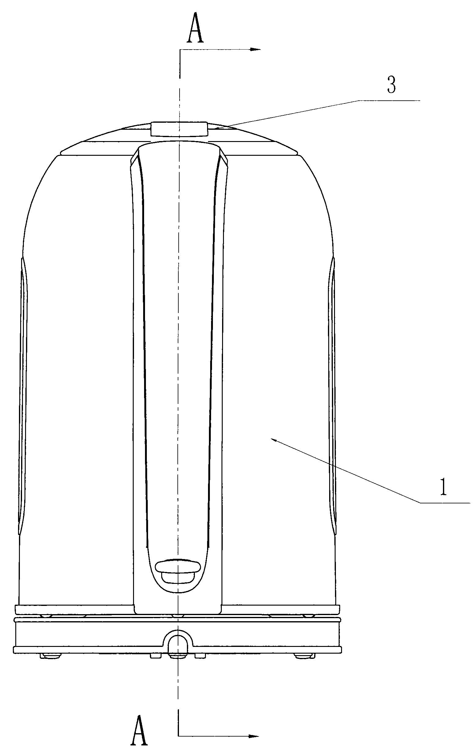
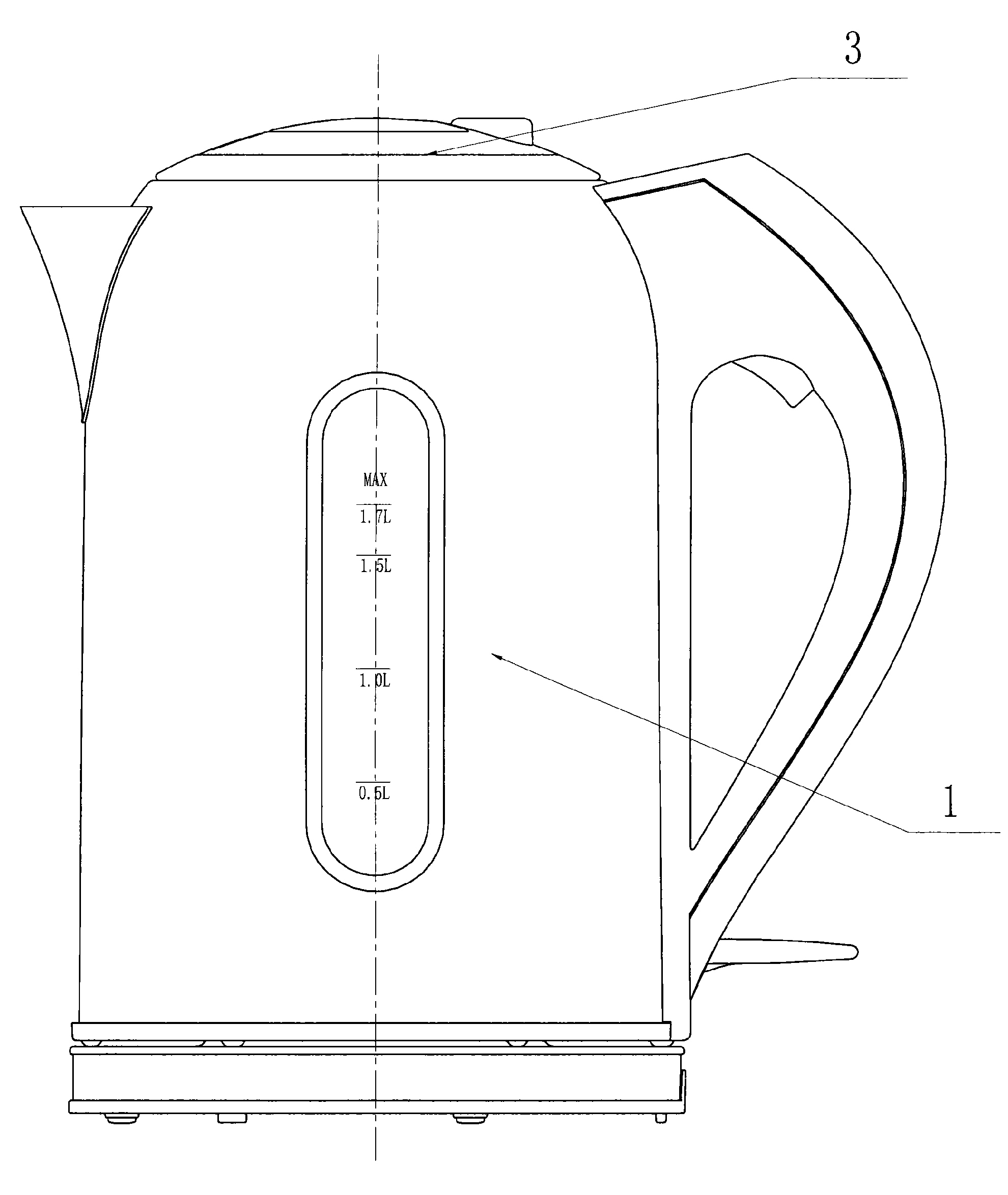
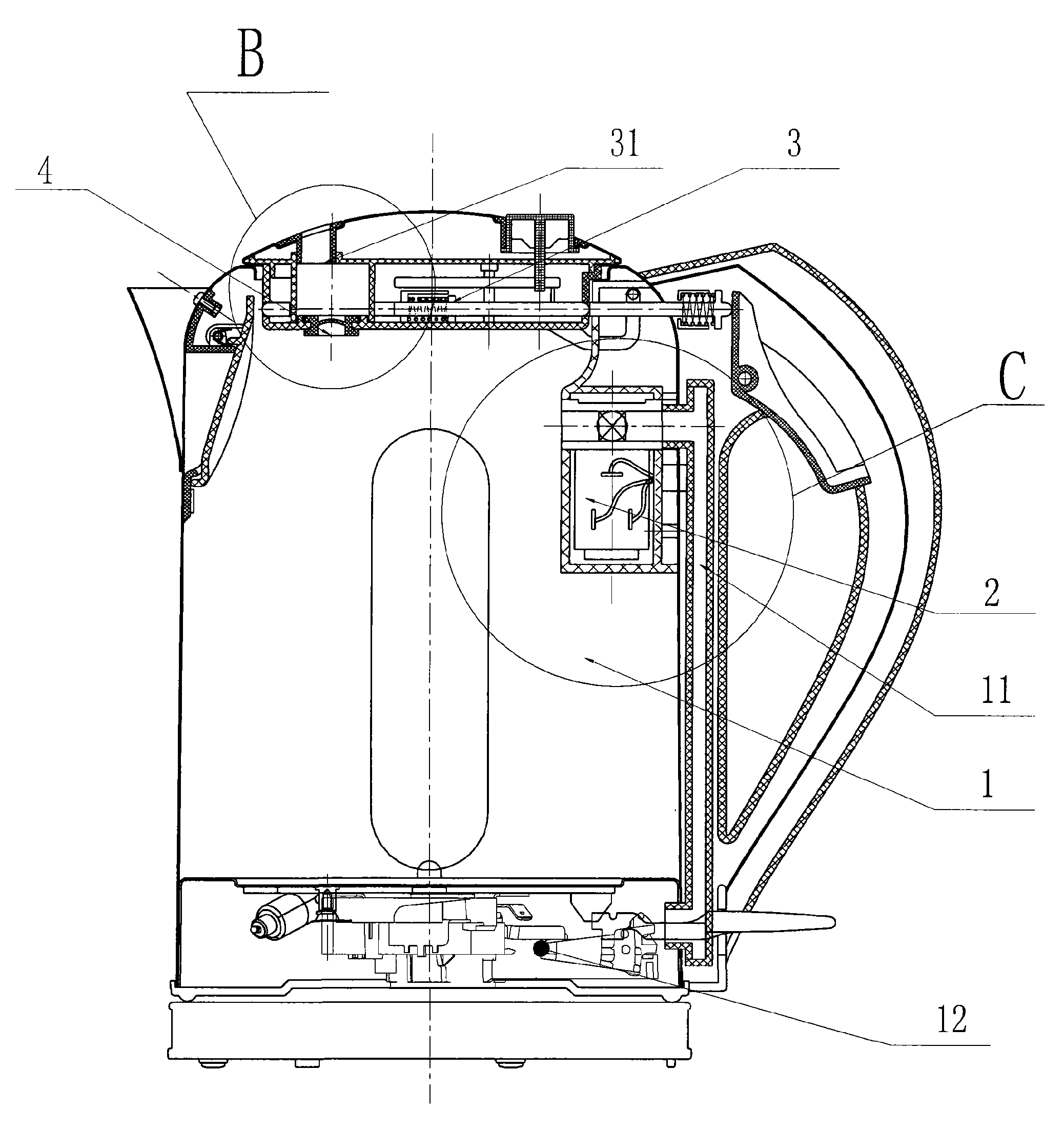
[0024] The structure diagram of the present invention is as figure 1 , 2 , 3, 4, 5, 6, and 7, including a pot body 1 and a pot cover 3, wherein the spout water hole of the pot body 1 is equipped with a spout sealing device 5, and the pot cover 3 is equipped with a pressure relief device. Device 4, the pot lid 3 is provided with a pressure relief hole 31 communicating with the atmosphere, the hollow cavity of the pot body 1 communicates with the pressure relief hole 31 on the pot lid 3 through the pressure relief device 4, and the handle of the pot body 1 is installed Water pouring control switch 16 is arranged, and the kettle spout sealing cover 5 is connected with an end of the driving device that controls it to open, and the other end of driving device is connected with pouring water switch 16.

[0025] In this embodiment, the above-mentioned driving device includes a connecting rod 32 arranged on the pot lid 3 and a push rod 15 arranged on the kettle body 1, one end of the...


PUM


Abstract

The invention provides an electric kettle, in particular to an electric kettle with a safety device. The electric kettle comprises a kettle body and a kettle cover, wherein a nozzle outlet of the kettle body is provided with a nozzle seal device; the kettle cover is assembled with a pressure relief device, and is provided with a pressure relief hole communicated with atmosphere; a hollow cavity of the kettle body is communicated with the pressure relief hole on the kettle cover through the pressure relief device; a handle on the kettle body is provided with a pouring control switch; the nozzle seal cover is connected with one end of a drive device which controls opening of the nozzle seal cover; the other end of the drive device is connected with the pouring switch. The nozzle seal device arranged on the nozzle outlet ensures that liquid in the kettle body can not flow out after the kettle body is turned over, thereby avoiding potential safety risk. When a user requires pouring water, the pour control switch on the handle is pressed which pushes the nozzle seal device to open and lets water flow out from the nozzle outlet. The electric kettle completely solves major potential safety risks of scalding of people, short circuit of electric appliance and the like which are caused by plenty liquid flowing out from the overturned kettle body, and has simple and reasonable structure, low manufacturing cost, safety and reliability operation and wide application range.

Description

technical field [0001] The invention relates to an electric kettle, in particular to an electric kettle with a safety device, which belongs to the transformation technology of the electric kettle. Background technique [0002] Most of the existing conventional wireless kettles use an open spout structure. When the kettle body is dumped, the liquid contained in the kettle body will flow out quickly, which can easily cause serious safety hazards such as burns to personnel and electrical short circuits. There are also electric kettles that take some measures to address the above problems. The structure used is to protrude a tongue-shaped sealing part from the spout of the kettle to prevent the water from falling over, but the disadvantage of this structure is that there is no pressure relief device in this structure. , The kettle body cannot be made completely closed. Such an electric kettle can only slow down the outflow speed of the liquid in the loaded kettle body when the ...

Claims


Application Information

Patent Timeline
Patent Type & Authority Applications(China)
IPC IPC(8): A47J27/21A47J36/00A47J36/06A47J36/14
CPCA47J27/21166
Inventor 郭建刚姚军陈永新
Owner GUANGDONG XINBAO ELECTRICAL APPLIANCES HLDG CO LTD
Learn More