LED lamp radiator with improved structure

A technology of LED lamps and radiators, which is applied to semiconductor devices of light-emitting elements, cooling/heating devices of lighting devices, electric solid devices, etc. It can solve problems such as breakage, failure to keep, increase costs and defective products, and achieve cost reduction , The effect of taking into account the production speed

Inactive Publication Date: 2009-10-21
陈德隆
View PDF0 Cites 0 Cited by
  • Summary
  • Abstract
  • Description
  • Claims
  • Application Information

AI Technical Summary

Problems solved by technology

[0003] First, each independent heat sink 10 is combined with each other, and the extension legs 14 of the front edge of the top spacer 11 and the bottom spacer 12 pass through the through hole 13 to be nested together, but the structure of the extension legs 14 is relatively thin, and it must be formed by The close cooperation between the assembler and the machine can make the extended leg 14 through the through hole 13 perform the clamping action of stretching and bending. It is easy to cause the machine to collide with the partially assembled heat sink 1 when another heat sink 10 is assembled. The extension leg 14 is broken, which affects the assembly quality and production speed, greatly increases the cost and defective products, and is not competitive in the market
[0004] Second, each independent heat sink 10 is combined into a heat sink 1, and the heat sink 1 is composed of at least sixteen heat sinks 10, so a heat sink 1 production line needs at least sixteen assemblers, a large amount of labor costs Expenditure reduces market competitiveness, and a problem in one process will affect the smoothness of the entire process and lower work efficiency
[0005] Third, the lower end surface of the radiator 1 is formed by sequentially arranging and combining the bottom spacers 12 of the radiator fins 10, which can be bonded to the aluminum substrate (not shown in the figure) of the LED lamp, but the upper end of the radiator 1 is Only by extending the legs 14 of the front edge of the top spacer 11 of each heat sink 10 to pass through the through hole 13 of the other sheet and then stretching out to form, because the radiator 1 itself dissipates heat by absorbing the high heat source of the LED lamp, so itself The heat is extremely high, and the extension legs 14 are too thin, which will cause the extension legs 14 to soften, deform and break. This will cause the upper parts of the heat sinks 10 to fit together, and the original design of equal intervals cannot be maintained, which will affect the heat dissipation effect and is not practical. sex at all

Method used


Image

  • LED lamp radiator with improved structure
  • LED lamp radiator with improved structure
  • LED lamp radiator with improved structure

Examples


Embodiment 1

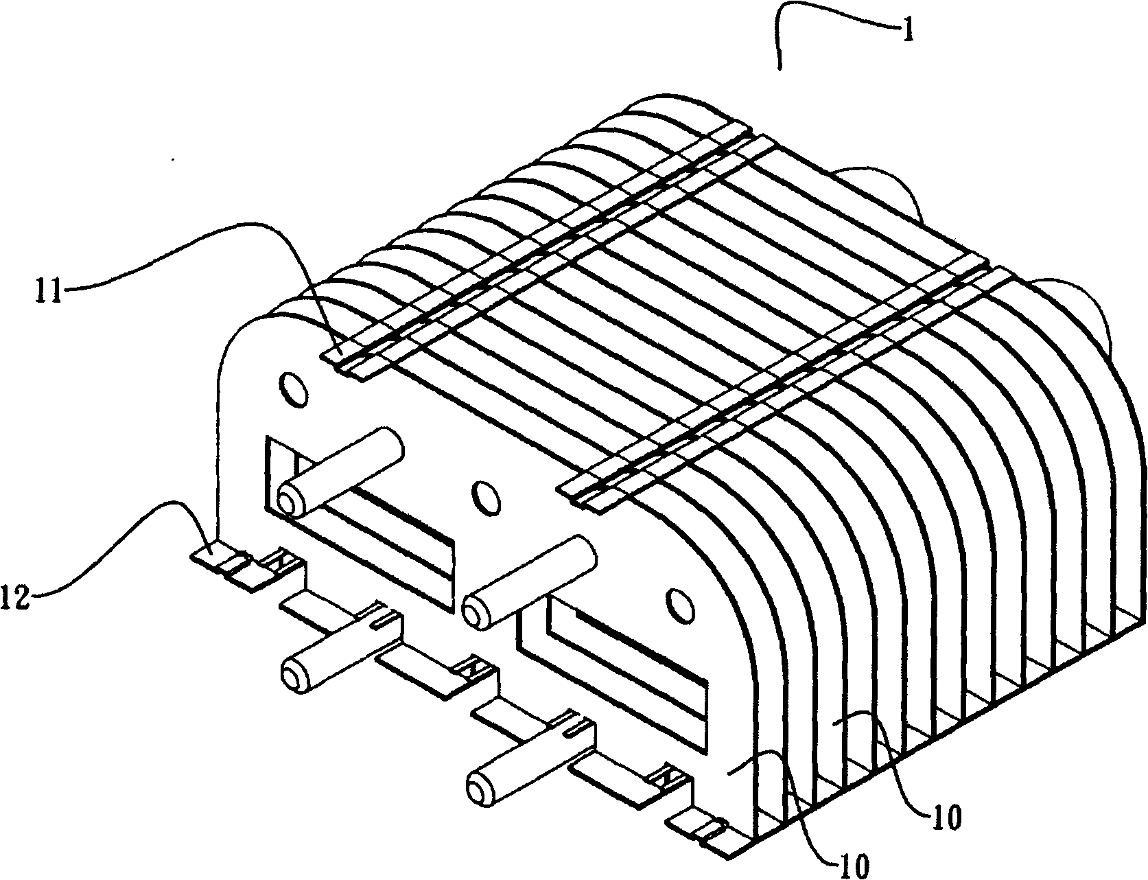
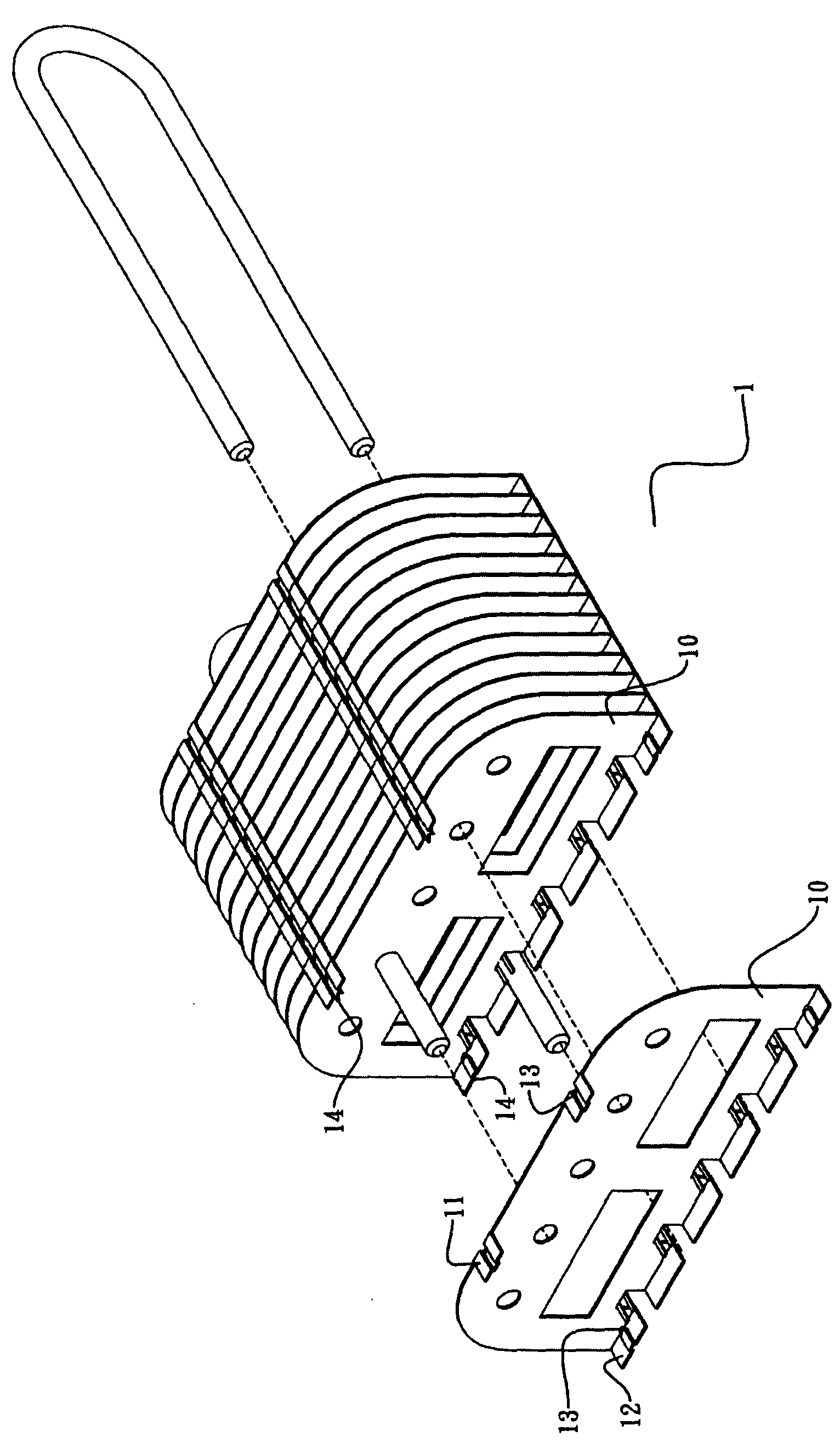
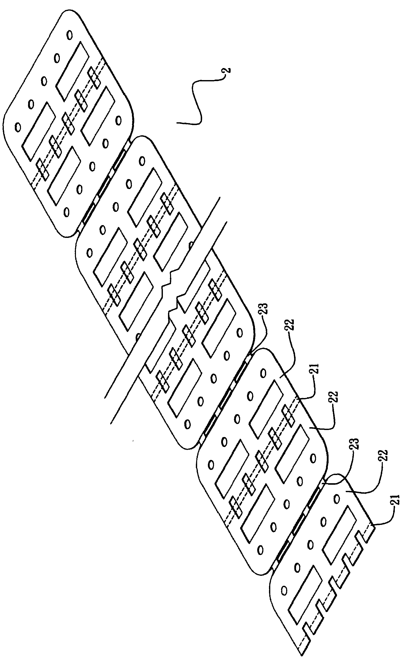
[0031] Improved structure of LED light radiator, refer to Figure 1 to Figure 5 , The radiator 3 includes a radiator, the radiator is formed by a long strip of heat-conducting material by a machine, the radiator includes a plurality of radiating units, the radiating units are connected into a whole, each radiating unit in turn from the bottom end surface The area 21, the wall end area 22, the top end area 23, and the wall end area 22 are integrally connected. After being formed, each wall end area 22 has the same interval length and is parallel to each other. The interval between the top end area 23 and the bottom end area 21 The length is the same and perpendicular to each wall end surface area 22, and the interval length of each wall end surface area 22 is greater than the interval length between the top end surface area 21 and the bottom end surface area 23.

Embodiment 2

[0033] Improved structure of LED light radiator, refer to Figure 6 with Figure 7 The heat sink 4 includes two heat sinks 40 and 41, and the structure of each heat sink is the same as the structure of the heat sink in the first embodiment. The two heat sinks 40 and 41 are superimposed and connected up and down, and the bottom end surface area of ​​the upper heat sink 40 of the two heat sinks is superimposed on the top end surface area of ​​the lower heat sink 41.

Embodiment 3

[0035] Improved structure of LED light radiator, refer to Figure 8 The radiator 5 includes two radiators. One radiator 50 has only two wall end areas 22 and a bottom end area 21 connected to the lower ends of the two wall end areas 22, and the other radiator has two wall end areas 22 The number is greater than two, and its structure is similar to the heat sink in the first embodiment. In addition, a chassis 52 is also included. The heat sinks are arranged parallel to each other on the chassis, and the wall end area 22 of each heat sink is perpendicular to the chassis. The surface of the chassis 52 is provided with a plurality of sets of corresponding and upwardly extending fixed feet 53. The two heat sinks are both placed on the chassis 52, and a set of fixed feet 53 is bent inward and pressed against the two wall end areas 22. One of the two ends of the bottom end surface area 21, so that the heat sink is fixed on the chassis 52.


PUM


Abstract

The invention relates to an LED lamp radiator with improved structure, which comprises at least one heating body; the heating body is mechanically shaped by a strip plate made from heat conduction materials, and comprises at least one heat dissipation unit; all the heat dissipation units are connected into a whole, and each heat dissipation unit is formed by the integrated connected of a bottom end surface area, a wall end surface area, a top end surface area and a wall end surface area in sequence; the wall end surface areas have identical interval length and are parallel to each other; the top end surface area and the bottom end surface area have the identical length and are vertical to the wall end surface areas; and the interval length of all the wall end surface areas is larger than that of the top end surface area and the bottom end surface area. The radiator is shaped by one-time operation by adopting a strip plate, manual operation is not need for assembling each component, both the quality and the production speed are considered, the cost is greatly lowered and the radiator has stronger market competitiveness.

Description

Technical field [0001] The present invention relates to the structure of an LED lamp, and specifically to an LED lamp heat sink with an improved structure. Background technique [0002] Refer to figure 1 , figure 2 , The existing LED lamp heat sink 1 is composed of multiple independent heat sinks 10 which are manually assembled one by one. The upper and lower ends of each independent heat sink 10 extend outwardly and have a top spacer 11 and a bottom spacer. 12. A through hole 13 is opened at the corners of the top spacer 11, the bottom spacer 12 and the heat sink 10. When two independent heat sinks 10 are combined, the through hole 13 can be provided in the top spacer 11 and the bottom spacer. The extension leg 14 on the front edge of the fin 12 passes through the rear and is externally fixed. This method of assembling the independent heat sink 10 is how to assemble the independent heat sink 10 one by one more easily and quickly. The focus of structural design. However, based ...

Claims


Application Information

Patent Timeline
Patent Type & Authority Applications(China)
IPC IPC(8): F21V29/00H01L23/367F21Y101/02F21V29/508F21V29/71F21Y115/10
Inventor 陈德隆
Owner 陈德隆
Why Eureka
Try Eureka