Fuel injection valve and method for producing a valve seat for a fuel injection valve

A fuel injection valve and fuel injection technology, which are applied in the direction of fuel injection devices, charging systems, engine components, etc., can solve the problem that the fuel injection valve cannot ensure a reliable and stable installation position of the nozzle side components, so as to avoid heat load, The effect of a solid and reliable connection

Inactive Publication Date: 2009-10-21
ROBERT BOSCH GMBH
View PDF2 Cites 2 Cited by
  • Summary
  • Abstract
  • Description
  • Claims
  • Application Information

AI Technical Summary

Problems solved by technology

With this arrangement there is the danger that a secure and stable mounting position of the nozzle side part in the valve seat carrier cannot be guaranteed over the service life of the fuel injection valve

Method used


Image

  • Fuel injection valve and method for producing a valve seat for a fuel injection valve
  • Fuel injection valve and method for producing a valve seat for a fuel injection valve
  • Fuel injection valve and method for producing a valve seat for a fuel injection valve

Examples


Embodiment Construction

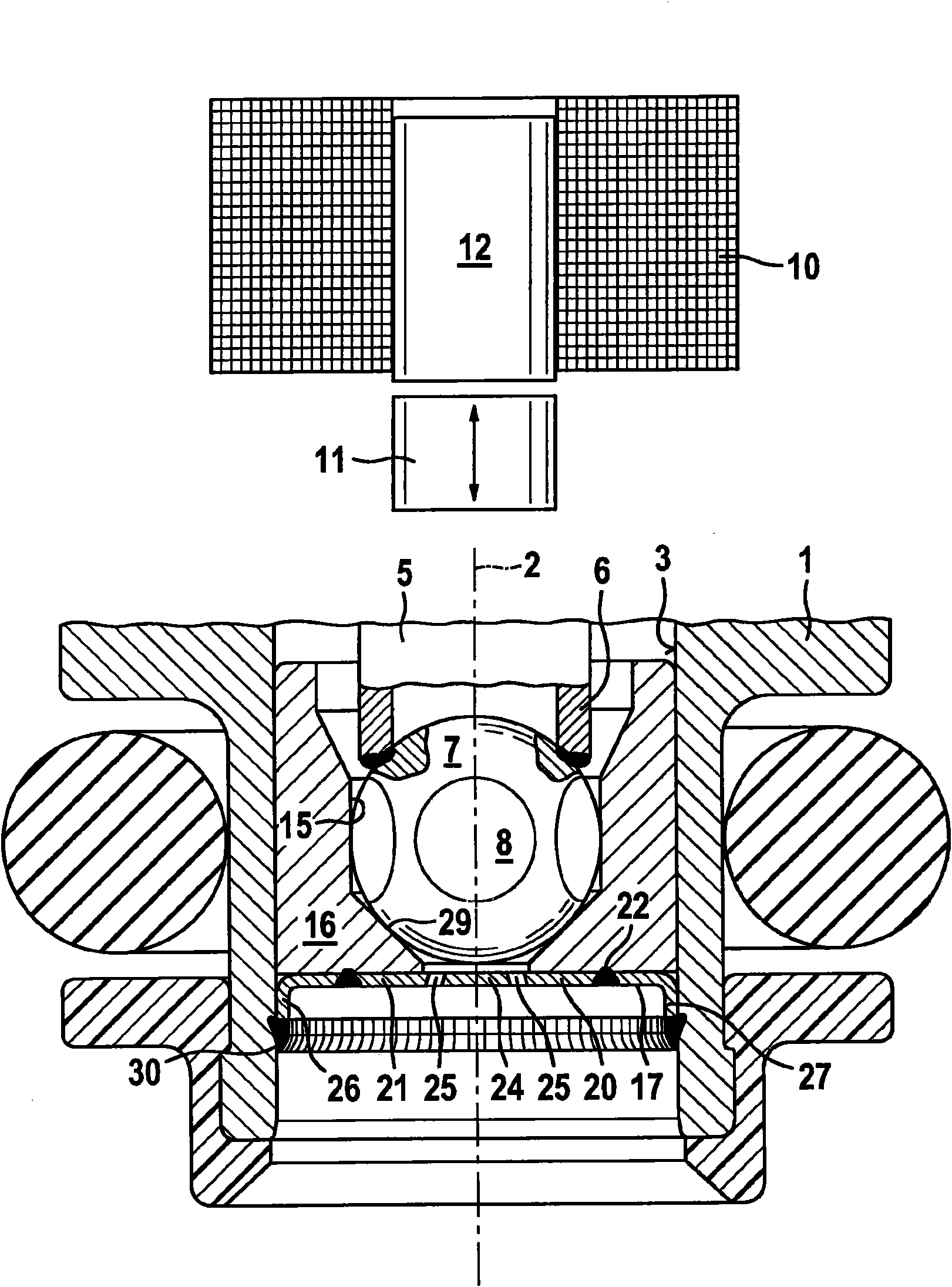
[0015] FIG. 1 partially shows a known valve in the form of an injection valve for a fuel injection system of a mixed-compression, forced-ignition internal combustion engine. The injection valve has a tubular valve seat carrier 1 in which a longitudinal bore 3 is formed concentrically with the valve longitudinal axis 2 . A for example tubular valve needle 5 is accommodated in the longitudinal bore 3 , which is connected at its downstream end 6 to a spherical valve closing body 7 , on the periphery of which for example five flattenings 8 are provided.

[0016] The operation of the injection valve takes place in a known manner, eg electromagnetically. However, piezoelectric or magnetostrictive actuators are also conceivable as excitation elements. A diagrammatically represented solenoid circuit with solenoid coil 10 , armature 11 and iron core 12 serves to move valve needle 5 axially and thus to open or close the injection valve against the spring force of a return spring (not s...


PUM


Abstract

The invention relates to a fuel injection valve which has a valve seat body (16) having a fixed valve seat face (29), wherein a valve closing body (7) interacts with the valve seat (29) for opening and closing the valve. The valve seat body (16) is accommodated in a longitudinal opening (3) of a valve seat carrier (1) and is connected fixedly to the latter. An atomizer attachment (121) is galvanically formed directly on a lower end surface (17) of the valve seat body (16) in a bonded manner. At least one ejection opening (125) which preferably widens in the manner of a funnel in the downstream direction is provided in the atomization attachment (121). The fuel injection valve is suitable, in particular, for use in fuel injection systems of mixture-compressing spark-ignition internal combustion engines.

Description

technical field [0001] The invention relates to a fuel injection valve of the type as claimed in independent claim 1 and to a method for producing a valve seat for a fuel injection valve of the type of independent claim 6 . Background technique [0002] A fuel injection valve is known from DE 4026721 A1 which has a spherical valve closing body which cooperates with a flat valve seat surface of the valve seat body. On the valve seat body, an injection orifice plate is fixedly connected to its downstream end face by means of welding seams. The valve seat piece, which is composed of the injection orifice plate and the valve seat body, is tightly fixed on the valve seat carrier body. The fixed connection between the valve seat part and the valve seat carrier is realized on the retaining edge of the injection orifice plate, which is under radial stress and has a circumferential weld seam. These seams are produced in particular by means of laser welding. [0003] A fuel injecti...

Claims


Application Information

Patent Timeline
Patent Type & Authority Applications(China)
IPC IPC(8): F02M61/18
CPCF02M61/1853F02M61/1806Y10T29/49401
Inventor J·哈肯贝格A·格洛克
Owner ROBERT BOSCH GMBH
Why Eureka
Try Eureka