Tension-chain sliding block and tension-chain head using same

A slider and zipper technology, applied in the application, sliding fastener components, fasteners and other directions, can solve the problems of many parts, complex structure, unfavorable zipper slider assembly operation, etc., to achieve simple operation, easy assembly, and simple structure. Effect

Active Publication Date: 2009-10-28
FUJIAN SBS ZIPPER SCI & TECH CO LTD
View PDF1 Cites 17 Cited by
  • Summary
  • Abstract
  • Description
  • Claims
  • Application Information

AI Technical Summary

Problems solved by technology

[0003] However, in order to realize the two functions of disassembling the pull tab and self-locking, the zipper slider needs to be provided with a self-locking horse hook and a gap closure respectively, which requires many parts and a relatively complicated structure, and is not conducive to the subsequent development of the zipper slider. assembly operation

Method used


Image

  • Tension-chain sliding block and tension-chain head using same
  • Tension-chain sliding block and tension-chain head using same
  • Tension-chain sliding block and tension-chain head using same

Examples


Embodiment Construction

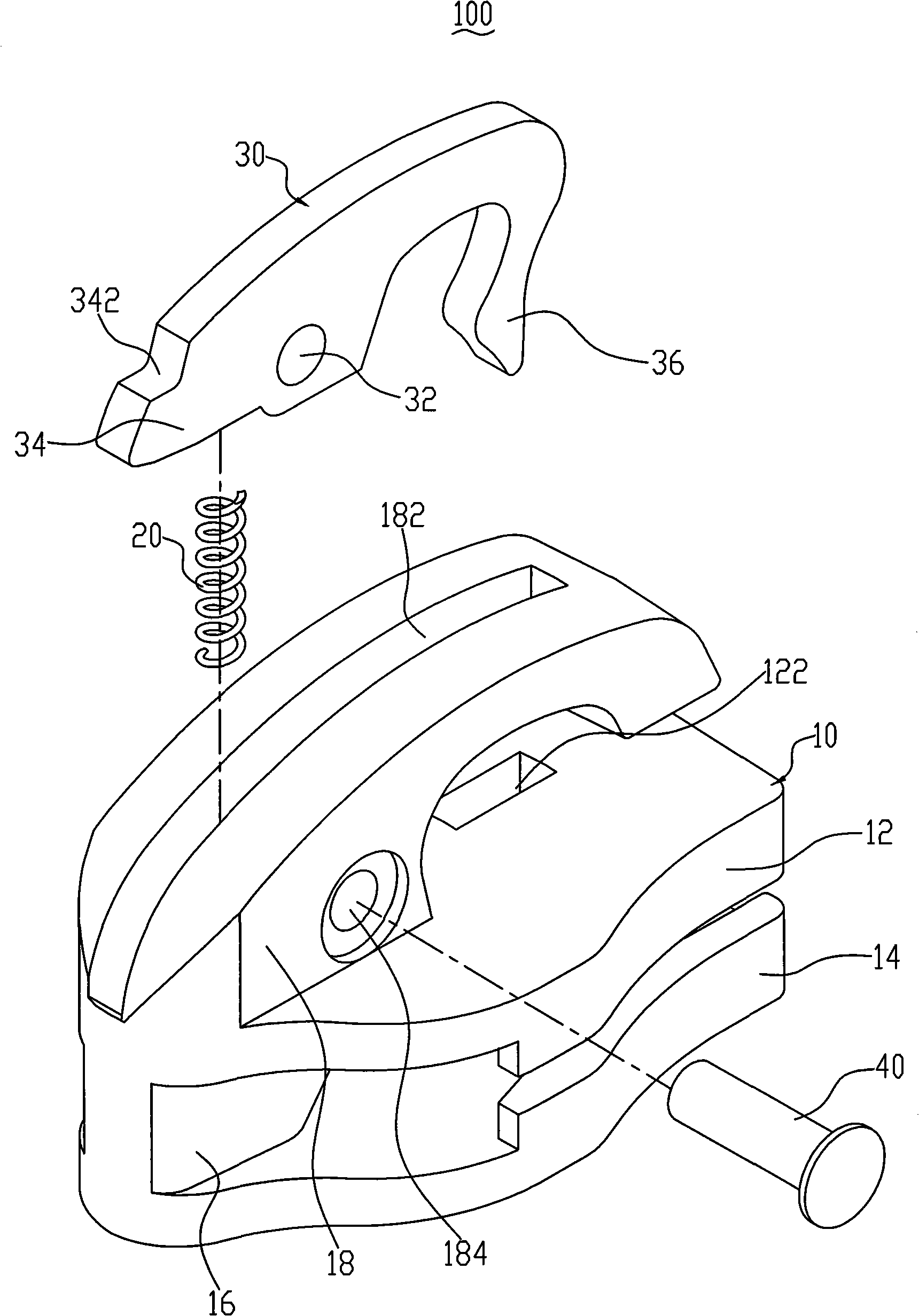
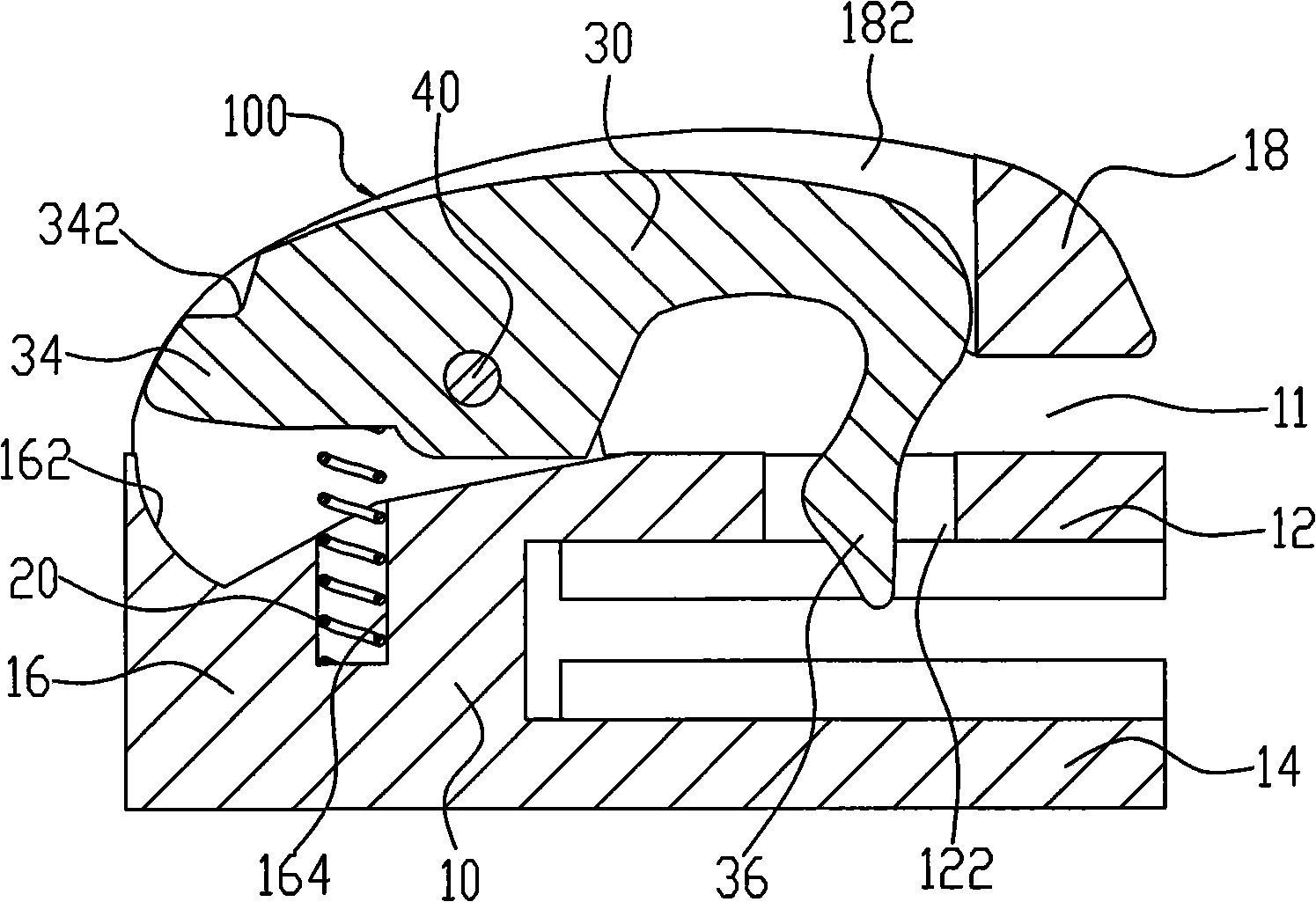
[0018] figure 1 Shown is a three-dimensional exploded view of the first embodiment of the slide fastener slider of the present invention. The zipper slider 100 includes a slider body 10 , an elastic element 20 , a self-locking element 30 and a rotating shaft 40 . The elastic element 20 and the self-locking element 30 are sequentially assembled on the slider body 10 (such as figure 2 and 3 shown).

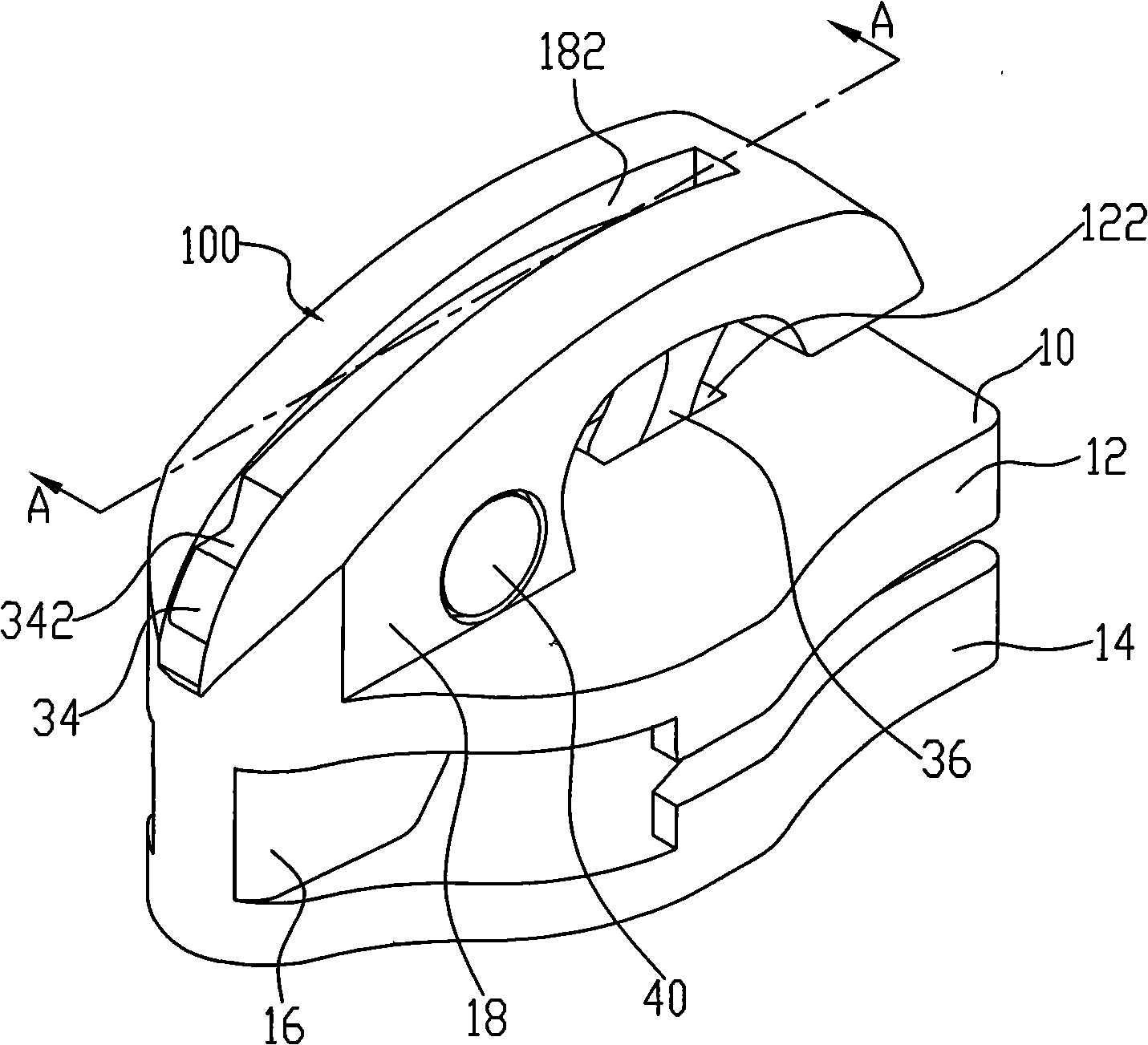
[0019] Please refer to figure 1 and image 3 , the slider body 10 includes an upper wing 12 and a lower wing 14, the upper wing 12 and the lower wing 14 are connected by a guide column 16, thereby forming a substantially Y-shaped slideway for a The sprocket (not shown) of the zipper passes through. The upper wing plate 12 is provided with a pull-tab stopper 18 and a through hole 122, the pull-tab stopper 18 has an arc-shaped elongated structure as a whole, and the through hole 122 is located behind the upper wing plate 12 relative to the guide post 16. end. One end of the p...


PUM


Abstract

The invention relates to a tension-chain sliding block and a tension-chain head using the same. The tension-chain sliding block comprises a sliding block, an elastic element and a self-locking element, wherein the sliding block is provided with a pulling piece block and a through hole, one end of the pulling piece block is connected with the sliding block, and the other end of the pulling piece block and the sliding block form a gap for a pulling rod of a pulling piece to pass through. The pulling piece block is provided with a through hole, the self-locking element is provided with a butt part and a hook part, the self-locking element can be rotatably pivoted into the through hole of the pulling piece block, the elastic element is respectively connected with the sliding block and the butt part of the self-locking element, elastic force is applied to the self-locking element to enable the hook part of the self-locking element to be inserted into the through hole of the sliding block; and in operation, the hook part of the self-locking element can be in the through hole of the sliding block by rotating the self-locking element to enable the pulling rod of the pulling piece to pass through. The tension-chain sliding block has the advantages of simple structure and convenient assembling, and the tension-chain head has the advantage of convenient operation.

Description

technical field [0001] The invention relates to a zipper slider and a zipper slider using the zipper slider, in particular to a self-locking zipper slider with a detachable pull piece and a zipper slider using the zipper slider. Background technique [0002] Currently, there are various self-locking zipper pullers with detachable pull tabs. On the one hand, these zipper pullers can complete the self-locking function of the chain belt during use, and on the other hand, allow users to disassemble and replace the pull tabs conveniently. For example, the patent No. 4,829,638 published on May 16, 1989 discloses a slider for a self-locking zipper pull with a detachable pull tab. The zipper slider has an upper wing and a lower wing, the upper and lower wings are connected by a guide post, and the upper wing is provided with a connecting lug above the guide post. The front end of an arc-shaped pull-tab holder is fixed on the connecting lug, and a gap is formed between its rear end...

Claims


Application Information

Patent Timeline
Patent Type & Authority Applications(China)
IPC IPC(8): A44B19/26
Inventor 骆燕明
Owner FUJIAN SBS ZIPPER SCI & TECH CO LTD
Why Eureka
Try Eureka