Lamp fitting for vehicle
A technology for lamps and vehicles, applied in road vehicles, motor vehicles, lighting and heating equipment, etc., can solve problems such as insufficient utilization, and achieve the effect of reducing depth and height dimensions
- Summary
- Abstract
- Description
- Claims
- Application Information
AI Technical Summary
Problems solved by technology
Method used
Image
Examples
Embodiment 1
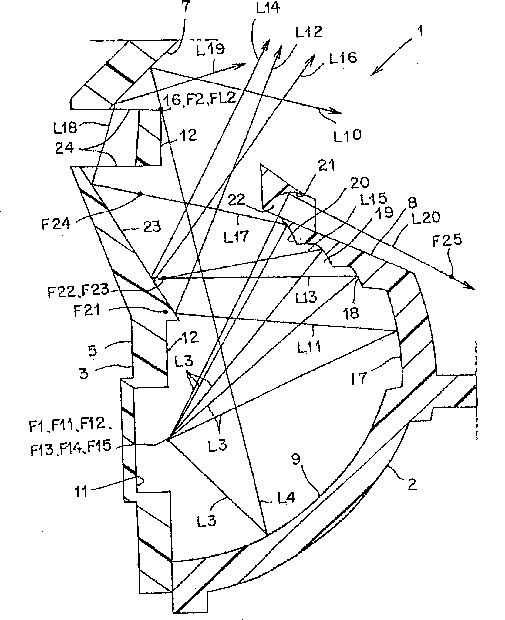
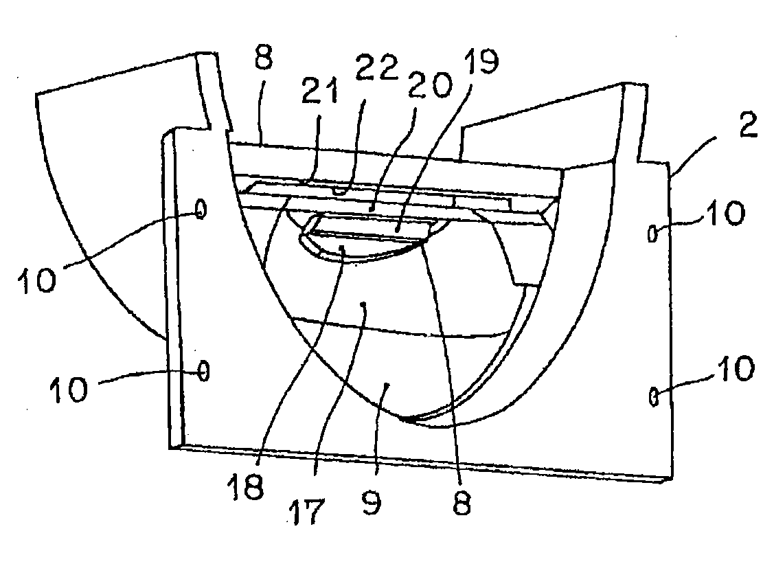
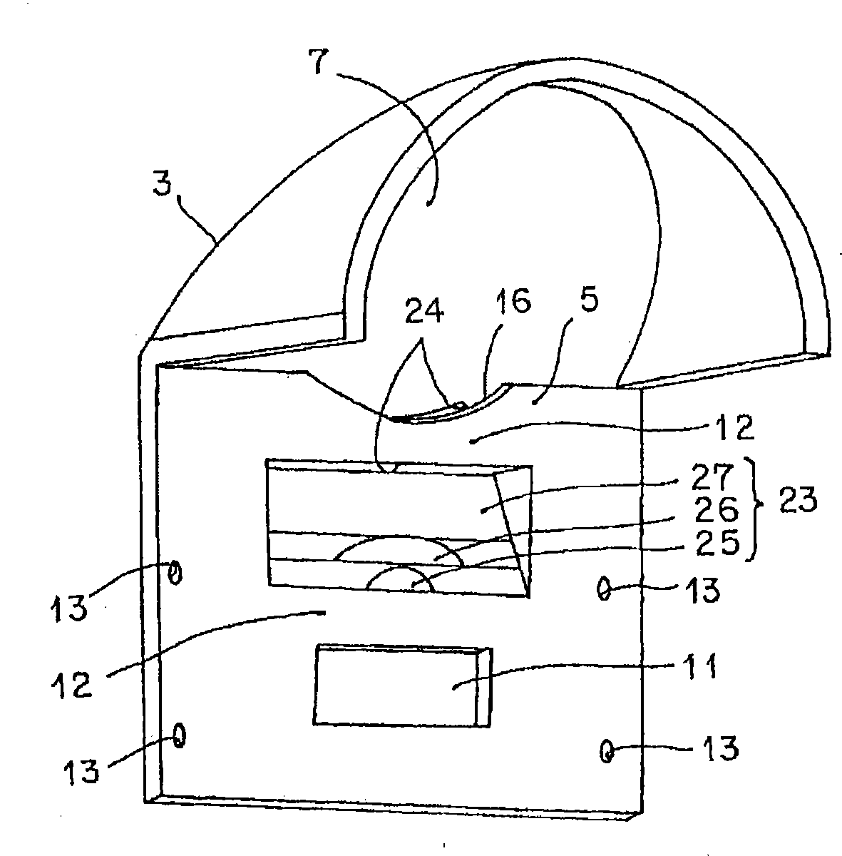
[0045] Figure 1 to Figure 7 Example 1 of the vehicle lamp of the present invention is shown. The configuration of the vehicle lamp of the first embodiment will be described below. In the drawings, reference numeral 1 is the vehicle lamp of the first embodiment. This example is, for example, a headlight for an automobile. The above vehicle lamp 1 includes a first reflector (main reflector, shade member and reflector) 2 on the front side, a second reflector (sub-reflector, lampshade and reflector) 3 on the rear side, a semiconductor-type light source 4, A lampshade 5, a projection lens (convex lens, condenser lens) 6, a plane reflection surface 7, a heat dissipation member (not shown), a light shielding member 8, a lamp housing and a lamp glass (for example, transparent external lens, etc.).
[0046] The first reflector 2 , the second reflector 3 , the semiconductor-type light source 4 , the lamp cover 5 , the projection lens 6 , the planar reflection surface 7 , the heat d...
Embodiment 2
[0094] Figure 8 as well as Figure 9 Example 2 of the vehicle lamp of the present invention is shown. in the figure, with Figure 1 to Figure 7 The same symbols denote the same components. Hereinafter, the vehicle lamp 1A of the second embodiment will be described.
[0095] The vehicle lamp 1A of the second embodiment has the second focal point of the second portion 18, the second focal point of the third portion 19, and the second focal point of the fourth portion 20 as a common or substantially common focal point F26 on the first additional reflection surface. , On the other hand, the common reflection surface 28 is provided on the second additional reflection surface at or near the above-mentioned common focal point F26. The common reflection surface 28 of the second additional reflection surface is composed of an elliptical reflection surface or other curved or plane reflection surfaces.
[0096] The vehicular lamp 1A of the second embodiment has the above-mentioned ...
Embodiment 3
[0099] Figure 10 ~ Figure 12 Example 3 of the vehicle lamp of the present invention is shown. in the figure, with Figure 1 to Figure 9 The same symbols denote the same components. Hereinafter, the vehicle lamp 1B of the third embodiment will be described.
[0100] In the vehicle lamp 1B of the third embodiment, the first additional reflection surface 29 for reflecting the light L3 from the semiconductor-type light source 4 in a predetermined direction is provided on the light shielding member 8 . Such as Figure 10 As shown, the above-mentioned first additional reflection surface 29 is composed of an elliptical reflection surface, and has a first focus F17 located at or near the first focus F1 of the first reflection surface 9, and a position above the first focus F17. The second focus of 27 . On the other hand, a second additional reflection surface 30 is provided on the globe 5 . The second additional reflection surface 30 is positioned near the second focal point 27...
PUM
 Abstract
Description
Claims
Application Information
 - R&D
- Intellectual Property
- Life Sciences
- Materials
- Tech Scout
- Unparalleled Data Quality
- Higher Quality Content
- 60% Fewer Hallucinations
Browse by: Latest US Patents, China's latest patents, Technical Efficacy Thesaurus, Application Domain, Technology Topic, Popular Technical Reports.
© 2025 PatSnap. All rights reserved.Legal|Privacy policy|Modern Slavery Act Transparency Statement|Sitemap|About US| Contact US: help@patsnap.com


