
Polarized light irradiation device for light aligning

A technology of irradiation device and polarized light, applied in optics, nonlinear optics, instruments, etc., can solve the problem that the orientation film cannot obtain orientation characteristics.

Active Publication Date: 2009-10-28
USHIO DENKI KK
View PDF6 Cites 25 Cited by
  • Summary
  • Abstract
  • Description
  • Claims
  • Application Information

AI Technical Summary

Problems solved by technology

[0038] In the irradiated area of ​​polarized light, if the illuminance of polarized light is not uniform or the direction of the polarization axis is deviated, there may be a part in the alignment film where the desired alignment characteristics cannot be obtained.

Method used


Image

  • Polarized light irradiation device for light aligning
  • Polarized light irradiation device for light aligning
  • Polarized light irradiation device for light aligning

Examples


Embodiment Construction

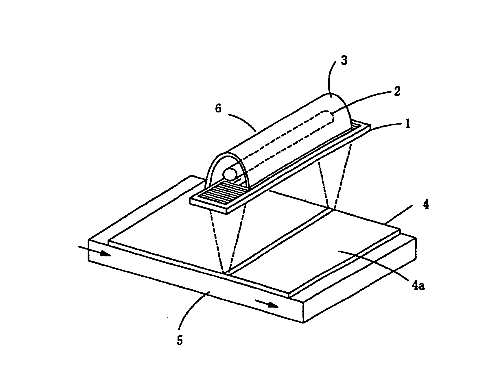
[0060] figure 1 A configuration example of a polarized light irradiation device according to an embodiment of the present invention is shown.

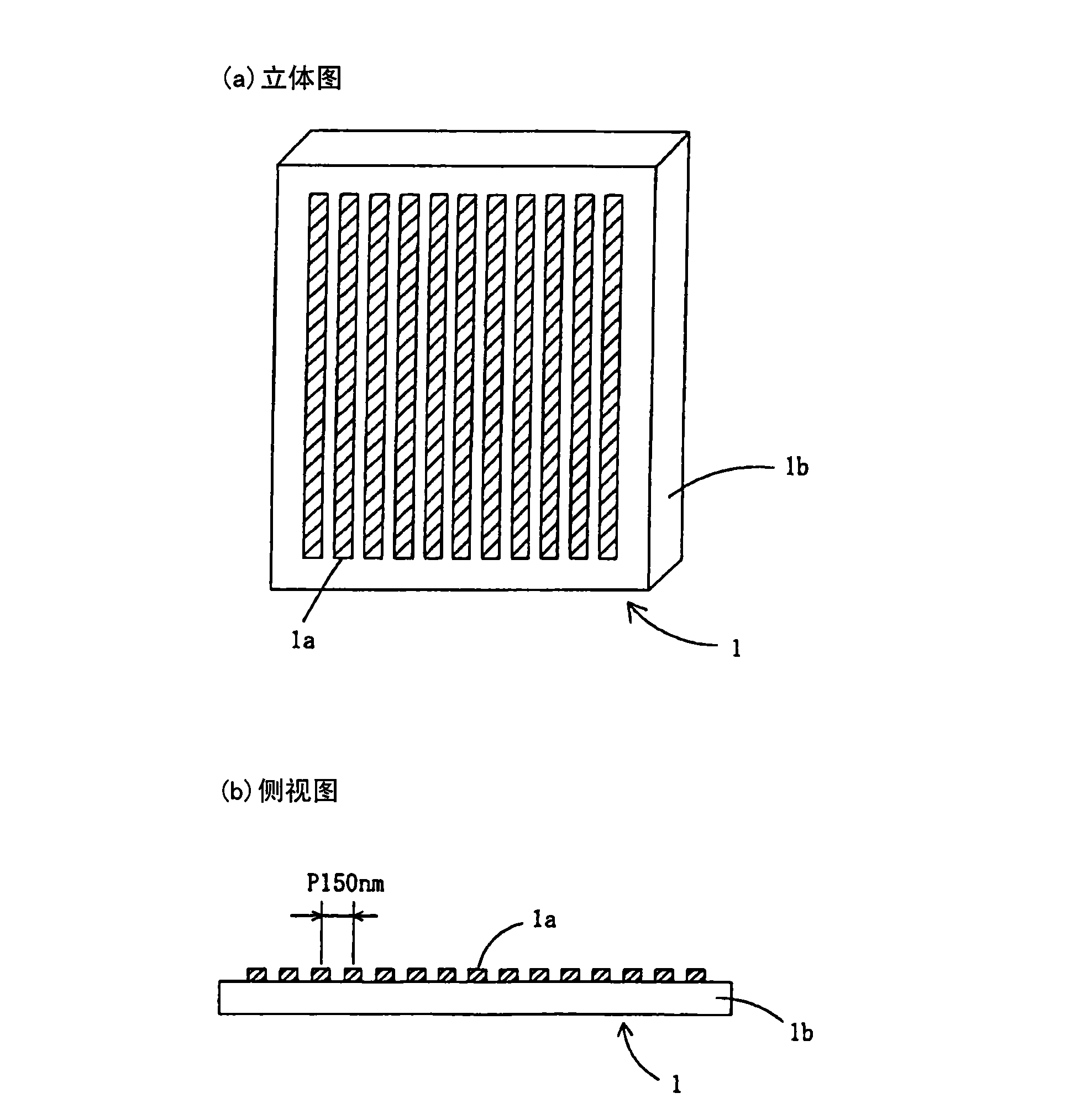
[0061] In the light irradiation section 6, with Figure 8 Similarly, rod-shaped lamps 2 such as high-pressure mercury lamps or metal halide lamps in which mercury is added as linear light sources, and trough-shaped reflectors 3 that reflect light from the lamps 2 are provided therein. In addition, a wire grid polarizing element 1 is provided on the light exit side. Here, a rod-shaped high-pressure mercury lamp or a metal halide lamp is known as a light source that emits light having a wavelength of 300 nm or less.

[0062] In addition, in figure 1 in, with Figure 8 The difference is that the workpiece 4 on which the photo-alignment film is formed is not a belt-shaped workpiece, but a panel substrate on which a photo-alignment film 4 a is formed on a light-transmissive substrate, and is placed on the workpiece platform 5 . The sen...


PUM

PropertyMeasurementUnit
wavelengthaaaaaaaaaa
heightaaaaaaaaaa

Abstract

The invention provides a polarized light irradiation device for light aligning, capable of getting polarized light with excellent extinction ratio in a wavelength region less than 300nm, furthermore, in the region, transmittance will not be changed and the polarization axis will not rotates even if the incident light to the polarization element has different angles. Workpieces (4) is conveyed facing to the direction of an arrow in the view, the light from a light irradiation part (6) is polarized by a wire grid type polarization element (1) and irradiates onto the workpieces (4) which is conveyed below the light irradiation part (6) for light aligning process. The grid of the wire grid type polarization element (1) is made from titanium oxide TiOx, can obtain polarized light with a extinction ratio above 15:1 in a range of wavelength from 240nm to 300nm, and in the region with wavelength under 300nm, the transmittance will not be changed even if the incident light to the polarization element has different angles, and the polarization axis will not rotate even if the incident light to the wire grid type polarization element has different angles.

Description

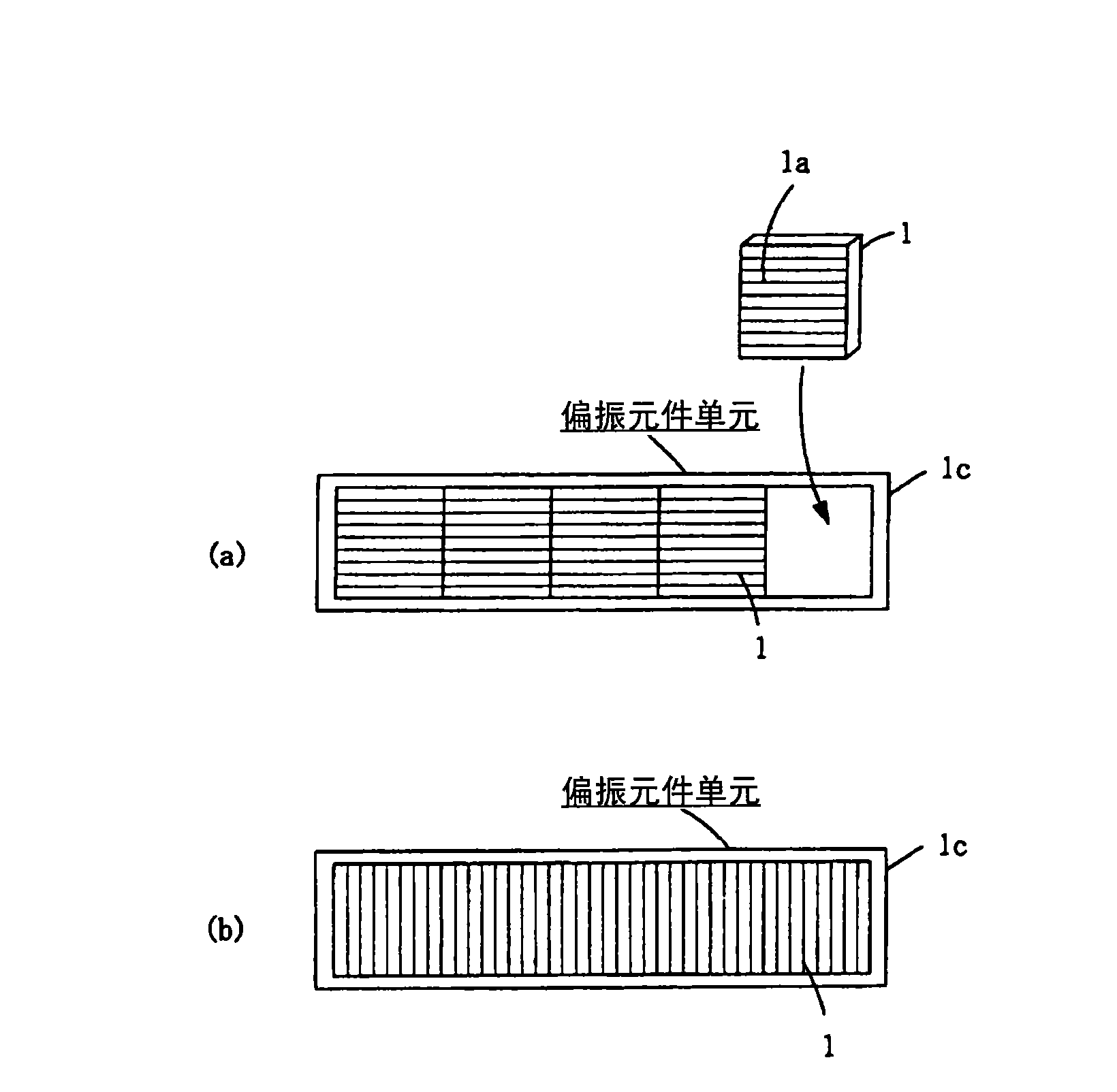
technical field [0001] The present invention relates to a polarized light irradiation device for optical alignment that irradiates polarized light of a predetermined wavelength to an alignment film of a liquid crystal panel or an alignment layer of a viewing angle compensation film, etc. Polarized light irradiation device for optical alignment obtained by combining polarizing elements. Background technique [0002] In recent years, a technique called photo-alignment in which polarized light of a predetermined wavelength is irradiated on an alignment film to align the alignment layer of a liquid crystal panel or an alignment layer of a viewing angle compensation film has been adopted. [0003] Hereinafter, the thin film provided with the alignment film or alignment layer aligned by the said light is collectively called a photo-alignment film. As the size of the photo-alignment film increases in size (for example, a quadrangle with a side of 2 m or more), the size of the pola...

Claims


Application Information

Patent Timeline
Patent Type & Authority Applications(China)
IPC IPC(8): G02F1/1337G02F1/1335
CPCG02F1/1303G02F1/133788
Inventor 盐谷纱由三宫晓史
Owner USHIO DENKI KK
Learn More