
Silicon photonic integrated circuit and fiber optic gyroscope apparatus using grating couplers

Active Publication Date: 2022-04-26
NAT SUN YAT SEN UNIV
View PDF22 Cites 0 Cited by
  • Summary
  • Abstract
  • Description
  • Claims
  • Application Information

AI Technical Summary

Benefits of technology

The invention provides a way to integrate multiple optical components onto a silicon chip, using grating couplers for input and output. This improves the efficiency of the chip and reduces signal distortion caused by polarization deviation. The use of grating couplers also results in lower optical insertion loss and parasitic interface light reflection, and helps stabilize the polarization direction of light. Overall, this highly integrated chip reduces the size and cost of production, and consumes less power than other systems.

Problems solved by technology

Such IFOG system configuration suffers from higher assembly cost, higher power consumption, and larger size.
Moreover, the connections between the discrete modules by the fiber leads cause phenomenon such as an additional parasitic interface light reflection, a higher optical insertion loss, and the shift of polarization direction with high environmental sensitivity.

Method used


Image

  • Silicon photonic integrated circuit and fiber optic gyroscope apparatus using grating couplers
  • Silicon photonic integrated circuit and fiber optic gyroscope apparatus using grating couplers
  • Silicon photonic integrated circuit and fiber optic gyroscope apparatus using grating couplers

Examples


Embodiment Construction

[0035]The detailed explanation of the invention is described as following. The described preferred embodiments are presented for purposes of illustrations and description, and they are not intended to limit the scope of the invention.

[0036]Terms used herein are only used to describe the specific embodiments, which are not used to limit the claims appended herewith. Unless limited otherwise, the term “a,”“an,”“one” or “the” of the single form may also represent the plural form.

[0037]It will be understood that, although the terms “first,”“second,”“third” and so on may be used herein to describe various signals and / or entities, these signals and / or entities should not be limited by these terms. These terms are only used to distinguish a signal and / or entity from another signal and / or entity.

[0038]The document may repeat reference numerals and / or letters in the various examples. This repetition is for the purpose of simplicity and clarity and does not in itself dictate a relationship be...


PUM


Abstract

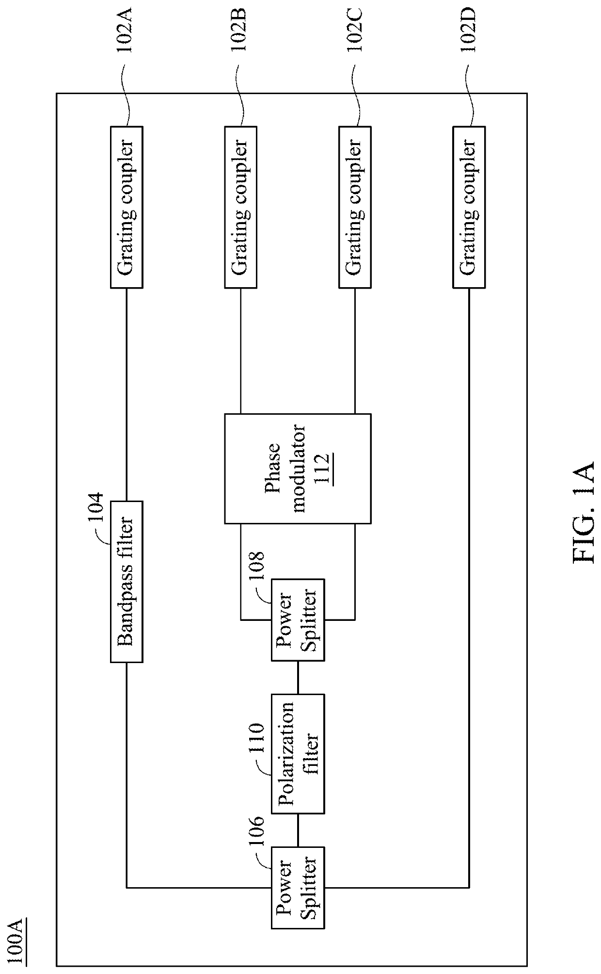
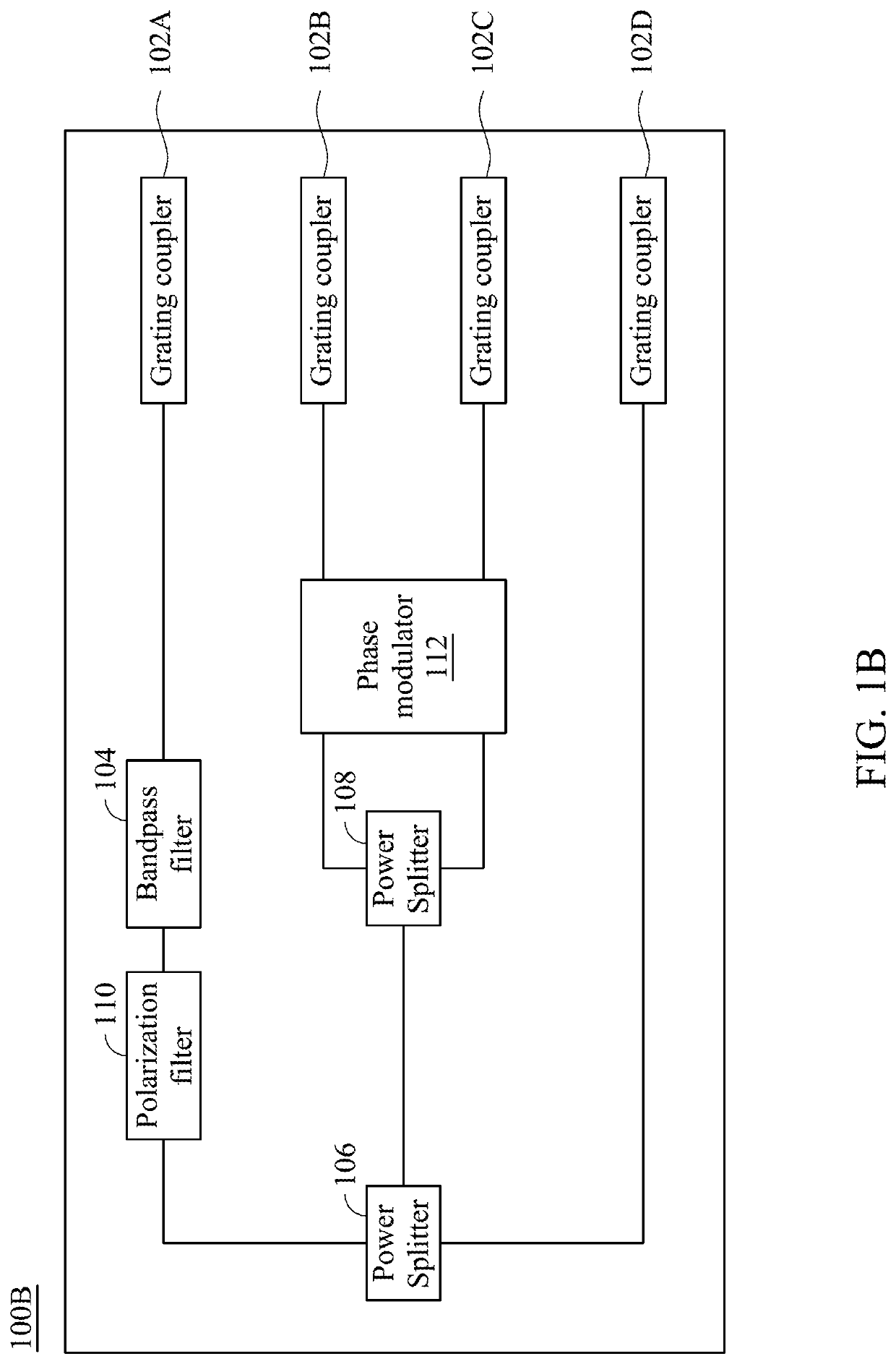
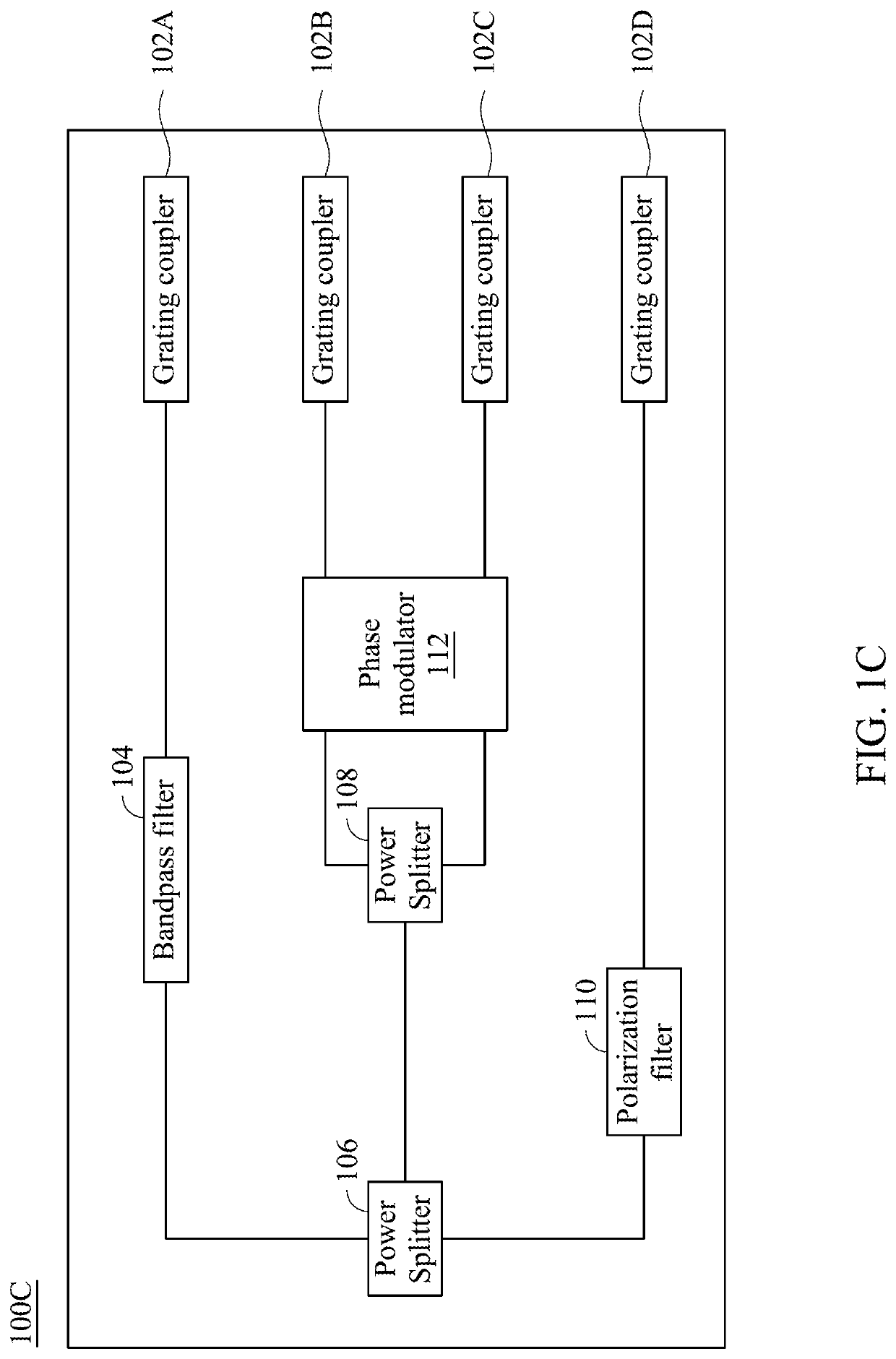
A silicon photonic integrated circuit is provided, which includes a first optical power splitter, a second optical power splitter, a first grating coupler and a second grating coupler. The first optical power splitter has an input, a first output and a second output, in which the input is configured to receive an inputted beam, and the first output is configured to output a returned beam. The second optical power splitter has an input, a first output and a second output, in which the input is coupled to the second output of the first optical power splitter. The first and second grating couplers are respectively coupled to the first and second outputs of the second optical power splitter, and are configured to optically couple two opposite ends of a fiber coil, respectively.

Description

RELATED APPLICATIONS[0001]This application claims priority to Taiwan Application Serial Number 109139810, filed on Nov. 13, 2020, which is herein incorporated by reference.BACKGROUNDField of the Invention[0002]The invention relates to a fiber optic gyroscope (FOG), and more particularly to a silicon photonic integrated circuit with grating couplers for optically connecting fiber coil(s) and an FOG apparatus having such silicon photonic integrated circuit.Description of Related Art[0003]At present, gyroscope technologies are mainly categorized into interferometric fiber optic gyroscopes (IFOGs), resonator fiber optic gyroscopes (RFOGs) and ring laser gyroscopes (RLGs). For the operation of the IFOG, a signal light with a broad wavelength range is generated by the light source and enters the main optical path through the optical power splitter, and then another optical power splitter is used to guide the signal light to the optical fiber coil in clockwise and counterclockwise directio...

Claims


Application Information

Patent Timeline
IPC IPC(8): G01C19/72G02B6/27G02B6/293
CPCG01C19/725G02B6/27G02B6/29304G02B6/30G02B6/124
Inventor HUNG, YUNG-JR
Owner NAT SUN YAT SEN UNIV
Learn More