
Variable gain amplifier

A gain amplifier, variable technology, applied in differential amplifiers, DC-coupled DC amplifiers, improving amplifiers to improve efficiency, etc., can solve problems such as affecting the next stage bias, achieve stable output current, reduce common mode Variation of output level, effect of reducing influence

Inactive Publication Date: 2009-10-28
苏州中科半导体集成技术研发中心有限公司
View PDF0 Cites 7 Cited by
  • Summary
  • Abstract
  • Description
  • Claims
  • Application Information

AI Technical Summary

Problems solved by technology

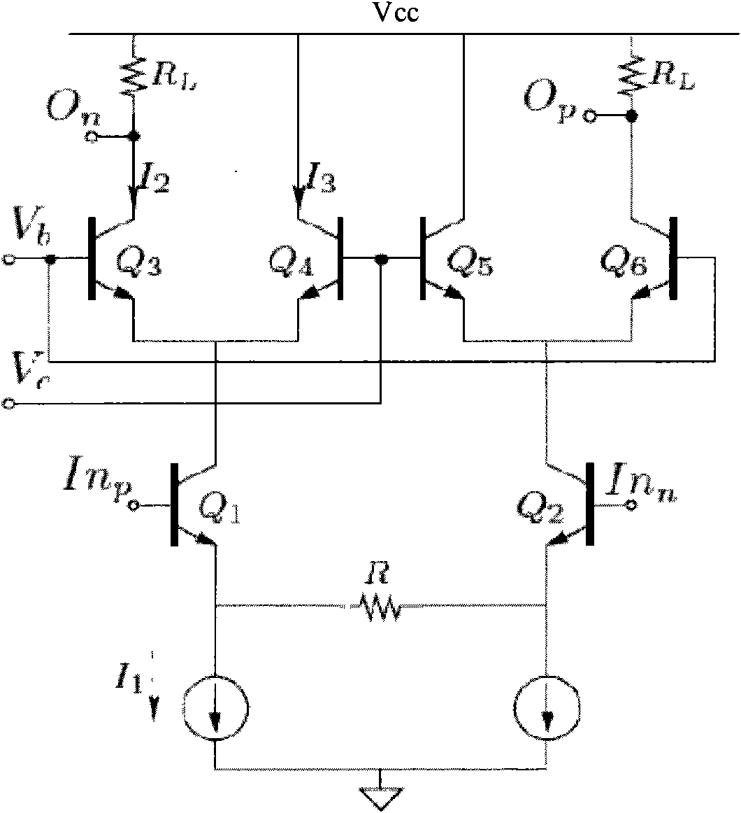
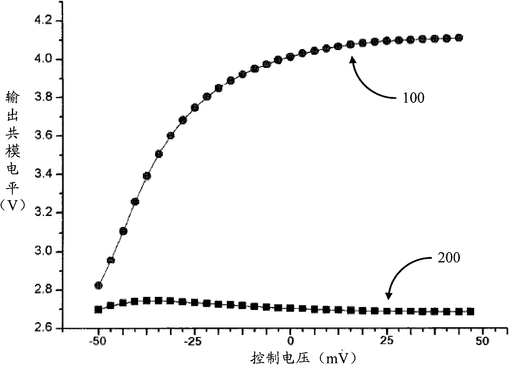
[0006] However, the above variable gain amplifier, in adjusting the control voltage V bc When its gain variation range is large, its common mode output level VO n 、VO p also changes significantly, thereby affecting the next-level bias

Method used


Image

  • Variable gain amplifier
  • Variable gain amplifier
  • Variable gain amplifier

Examples


Embodiment Construction

[0013] Based on the gain formula (1) of the above-mentioned prior art variable gain amplifier, it can be seen that the prior art variable gain amplifier changes the control voltage V bc , to change the gain G. However, in order to make the variation range of the gain G larger, it is necessary to make the control voltage V bc The change is large, that is, V b and V c The change is also large, correspondingly, I 2 The range of variation is also large, about the current source current I 1 ~0.

[0014] Based on the circuit structure of the above-mentioned prior art variable gain amplifier, its common mode output level is:

[0015] VO n =VO p =V cc -I 2 × R L . (2)

[0016] Based on the formula (2), it can be seen that the variation range of the common mode output level is about Vcc~Vcc-I 1 ×RL. When the current source current I 1 When the product I1×RL with the load resistance RL is relatively large, such as several hundred millivolts or even about 1V, the common-mo...


PUM


Abstract

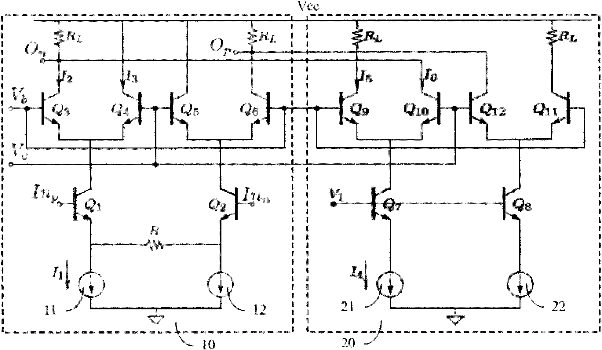
The invention discloses a variable gain amplifier, which comprises a current adjustable amplifying circuit and a compensating circuit; wherein the current adjustable amplifying circuit can change the gain according to a control voltage; while the output terminal of the compensating circuit is connected with the output terminal of the current adjustable amplifying circuit, and provides direct compensating current to the adjustable amplifying circuit; the sum of the direct compensating current and the output current of the current adjustable amplifying circuit is equal to the current source current of the current adjustable amplifying circuit. The output current of the variable gain amplifier is relatively stable, which reduces the change of a common mode output level, thereby reducing the influence on the next-stage circuit offset.

Description

technical field [0001] The invention relates to the communication field, in particular to a variable gain amplifier applied in the transceiver link of the communication system. Background technique [0002] Variable Gain Amplify (VGA, Variable Gain Amplify) is a commonly used module in communication circuits. Its main function is to adjust the gain of the transceiver link so that the output signal amplitude is basically stable when the input signal amplitude changes greatly, which is convenient for subsequent processing modules. Reprocess the signal. After the RF signal is down-converted by a down-conversion mixer, the resulting baseband signal is usually amplified by a baseband variable gain amplifier (BBVGA). In order to obtain a certain output amplitude, the baseband variable gain amplifier is usually designed in a multi-stage form, and a baseband channel selection filter is inserted between the stages. Therefore, the output of the first stage baseband variable gain amp...

Claims


Application Information

Patent Timeline
Patent Type & Authority Applications(China)
IPC IPC(8): H03F3/45G05F3/08H03F1/02H03F3/04H04B1/00
Inventor 胡雪青代伐
Owner 苏州中科半导体集成技术研发中心有限公司
Learn More