Capacitance microphone

A technology of condenser microphones and electrodes, which is applied in the direction of electrostatic transducer microphones, etc., can solve the problems of high mass production cost and complicated manufacturing process, and achieve the effects of large synovial film damping, reduced process difficulty, and reduced cost

Inactive Publication Date: 2009-10-28
AAC ACOUSTIC TECH (SHENZHEN) CO LTD +1
View PDF0 Cites 19 Cited by
  • Summary
  • Abstract
  • Description
  • Claims
  • Application Information

AI Technical Summary

Problems solved by technology

[0003] Micro-Electro-Mechanical-System Microphone (MEMS for short) is currently the most widely used microphone with better performance. In related technologies, the backplane is located b

Method used


Image

  • Capacitance microphone
  • Capacitance microphone
  • Capacitance microphone

Examples


Embodiment Construction

[0020] The present invention will be further described below in conjunction with the accompanying drawings and embodiments.

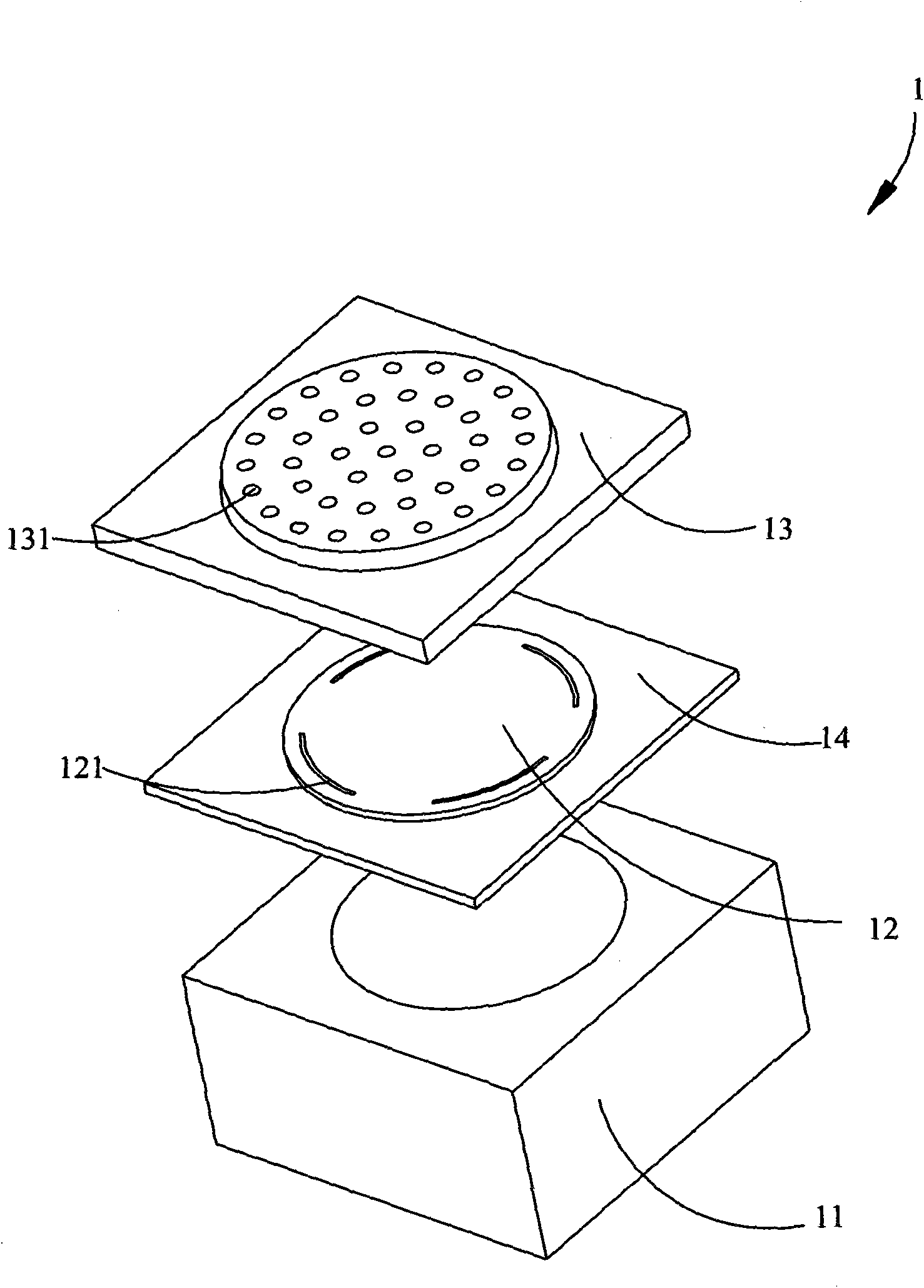
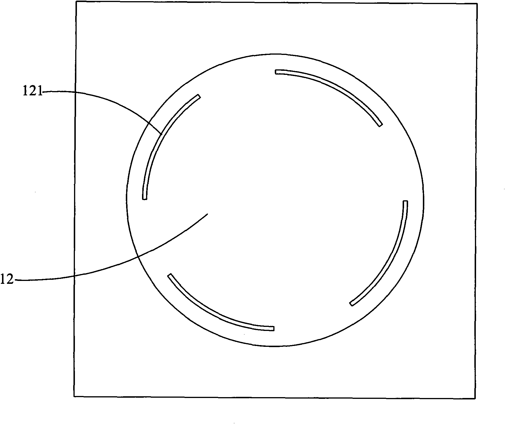
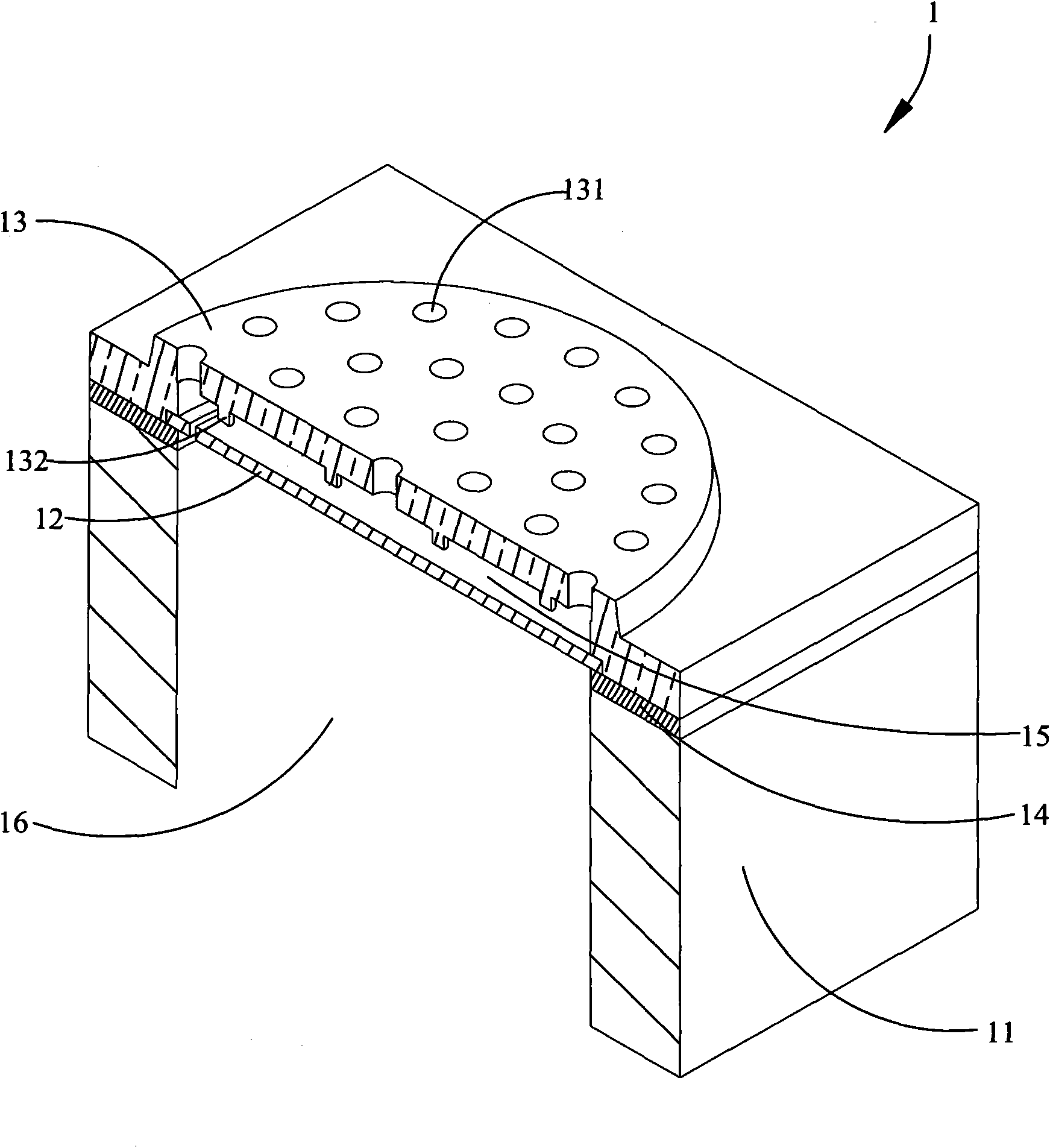
[0021] see figure 1 and image 3 , in one embodiment provided by the present invention, condenser microphone 1 comprises the substrate 11 that is provided with cavity 16, the supporting layer 14 that is connected with substrate 11, the back plate 13 that is arranged on the supporting layer 14 and diaphragm 12, the back plate 13 is set opposite to the diaphragm 12, the back plate 13 is provided with an acoustic hole 131, the diaphragm 12 is located between the back plate 13 and the base 11, and the diaphragm 12 is provided with a hole 121 passing through the diaphragm. The condenser microphone 1 further includes a first electrode (not shown) coupled to the back plate 13 and a second electrode (not shown) coupled to the diaphragm. There is an air gap 15 between the diaphragm 12 and the back plate.

[0022] An anti-adsorption device is provided between ...


PUM


Abstract

The present invention provides a capacitance microphone, which includes a substrate equipped with a cavity, a back board equipped with sound hole and connected with the substrate, the first electrode coupled with the back board, and also includes a diaphragm which is opposite to the back board and located between the back board and the substrate, the second electrode coupled with the diaphragm, wherein air gap is between the diaphragm and the back board, and the diaphragm is equipped with a hole through the diaphragm. The capacitance microphone has the advantages of reduced difficulty of manufacturing technology and low bulk production cost.

Description

technical field [0001] The invention relates to a condenser microphone, in particular to a micro-electromechanical microphone. Background technique [0002] With the development of wireless communication, there are more and more mobile phone users around the world. The requirements of users for mobile phones are not only satisfied with calls, but also to be able to provide high-quality call effects. Especially the current development of mobile multimedia technology, the mobile phone Call quality is more important. The microphone of a mobile phone is used as a voice pick-up device for the mobile phone, and its design directly affects the call quality. [0003] Micro-Electro-Mechanical-System Microphone (MEMS for short) is currently the most widely used microphone with better performance. In related technologies, the backplane is located between the diaphragm and the base, so the manufacturing process is complicated. , and the mass production cost is high, so it is necessary ...

Claims


Application Information

Patent Timeline
IPC IPC(8): H04R19/04
Inventor 颜毅林葛舟
Owner AAC ACOUSTIC TECH (SHENZHEN) CO LTD
Why Eureka
Try Eureka