Exercise aid device

An auxiliary equipment and sports technology, applied in sports accessories, passive exercise equipment, gymnastics equipment, etc., can solve the problems of unable to train muscle coordination, unable to pass, etc.

Inactive Publication Date: 2009-10-28
PANASONIC CORP
View PDF1 Cites 6 Cited by
  • Summary
  • Abstract
  • Description
  • Claims
  • Application Information

AI Technical Summary

Problems solved by technology

This kind of movement linking the foot movement during walking with the different angles of the ankle joint cannot be realized by the device in Patent Document 1
Therefore, for the exercise assisting device in Patent Document 1, it is impossible to train the coordination between muscles in rehabilitation training

Method used


Image

  • Exercise aid device
  • Exercise aid device
  • Exercise aid device

Examples


no. 1 approach

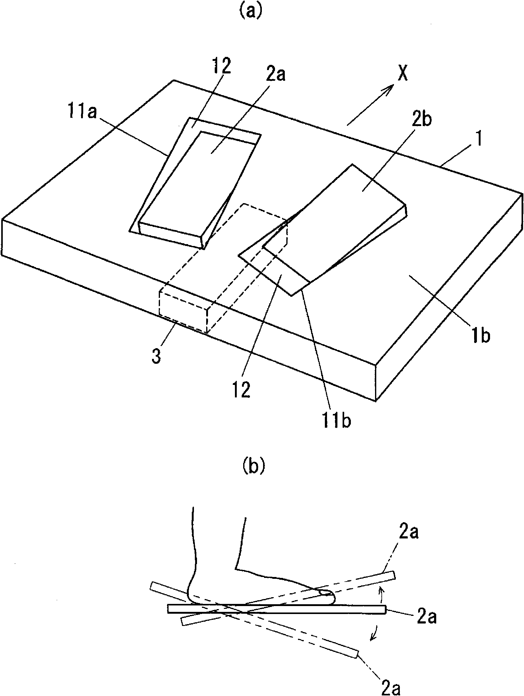
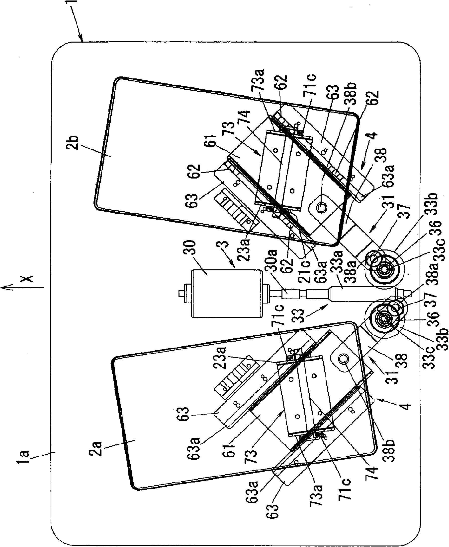
[0052] Although this embodiment shows a device adapted to be placed on the floor, the device may be used with its parts buried in the floor. A choice can be made between placing the device in a fixed location or supporting it in a removable manner. Such as figure 1 and figure 2 As shown, in this embodiment, the exercise assistance device includes a housing so as to be placed on the floor. The housing 1 is designed to have a cuboid shape. Base plate 1 a is shown as housing 1 in the illustration. However, the housing 1 is not limited to a rectangular parallelepiped shape. To simplify the description hereinafter, the housing 1 is shown to have a top surface parallel to the floor when it is placed on the floor. therefore, figure 1 UP and DOWN in indicate the upper and lower sides in use, respectively. When used in a state of being partially buried in a floor, the housing 1 may have a frame structure excluding the upper plate 1b.

[0053] The housing 1 is provided with lef...

no. 2 approach

[0088] In the present embodiment, the exercise assisting device has slide drive means 31 and swing drive means 32 respectively different from the slide drive means 31 and swing drive means 32 shown in the first embodiment. In addition, the left foot support 2a and the right foot support 2b each have a representative part. These representative positions are points that do not shift when the angle formed by the top surface of the left foot support 2a and the top surface of the housing 1 is changed and when the angle formed by the top surface of the right foot support 2b and the top surface of the housing 1 is changed. Defined by points that do not shift when changing. Multiple points are regarded as such representative sites. However, each of these points can be used as a representative site. That is, the exercise assisting device has a left foot support 2 a and a right foot support 2 b that slide along the top surface of the housing 1 . For this reason, the exercise assistin...

Embodiment approach 3

[0118] The present embodiment is basically the same as the first embodiment except for the configurations of the slide drive device 31 and the swing drive device 32 . Such as Figure 13 As shown, the swivel drive unit 32 includes a pair of side plates 22 depending from respective two lateral sides of the left and right foot supports 2a and 2b. Each side plate 22 is formed with a cam notch 23 extending transversely through the side plate 22 . Two guide rods 24 are fixed to the housing 1 and extend through the cam slot 23 . The sliding drive device 31 has the same configuration as that of the second embodiment, and has an eccentric rotor 34 that receives a turning force from the branching device 33 and a crank connecting rod 35 that is coupled at one end to the eccentric rotor 46 And the other end is coupled to the corresponding one of the left and right pedals 2a and 2b through the crank journal 35b.

[0119] The cam notch 23 is inverted V-shaped, and its two ends are lower ...


PUM


Abstract

The invention provides an exercise aid device. A housing 1 is provided with a left foot support 2a and the right foot support 2b each of which is provided for bearing the user's foot thereon. A drive unit 3 is configured to vary an upper surface angle of each of the left foot support 2a and the right foot support relative to horizontal plane. Each of the left foot support 2a and the right foot support 2b is driven to move within a swing range. When one of the left foot support 2a and the right foot support 2b has its front end being located at an upper end of the swing range, the other of the left foot support 2a and the right foot support 2b has its front end being located at a lower end of the swing range. Both of a left ankle joint and a right ankle joint are alternately dorsiflexed and plantarflexed. Consequently, it is possible to obtain an exercise assisting device being configured to bend and stretch lower legs to stimulate lower leg muscles.

Description

technical field [0001] The present invention relates to an exercise assisting device that helps users stretch their leg muscles mainly in a standing posture by means of an external force. Background technique [0002] In the past, various types of exercise assisting devices have been proposed, which help users stretch their muscles without effort but by means of external force applied to the user to achieve exercise effects. These devices are known to fall into two types, one configured to apply a force that bends the user's joint so as to stretch the muscles associated with the joint, and the other configured to apply stimulation to the user's body to induce a nerve reflex , thereby forcing the associated muscle to stretch. [0003] Additionally, these devices are designed to require the user to assume different positions depending on the muscles being stretched. An example of such a device is for the prevention of osteoarthritis or for walking training by the user imitat...

Claims


Application Information

Patent Timeline
Patent Type & Authority Applications(China)
IPC IPC(8): A61H1/02A63B23/08A63B23/10A63B24/00
CPCA61H1/0237A61H1/0262A61H1/0266A63B23/04A63B23/10A61H1/02A63B24/00
Inventor 越智和弘四宫叶一小泽尚久后藤孝夫斋藤笃裕菅井春夫
Owner PANASONIC CORP
Why Eureka
Try Eureka