Sloping plate sedimentation tank for lateral rotational flow sludge discharge

A technology of inclined plate sedimentation and flow discharge, applied in the field of sedimentation tanks, can solve problems such as poor sludge discharge effect, and achieve the effect of slow settling speed, enhanced sludge discharge effect, and good effect.

Inactive Publication Date: 2011-01-12
HARBIN INST OF TECH +1
View PDF1 Cites 0 Cited by
  • Summary
  • Abstract
  • Description
  • Claims
  • Application Information

AI Technical Summary

Problems solved by technology

[0004] In order to solve the problem of poor mud discharge effect of the existing sloping plate sedimentation tank, the present invention further provides a sloping plate sedimentation tank with side swirl flow mud discharge

Method used


Image

  • Sloping plate sedimentation tank for lateral rotational flow sludge discharge
  • Sloping plate sedimentation tank for lateral rotational flow sludge discharge
  • Sloping plate sedimentation tank for lateral rotational flow sludge discharge

Examples


specific Embodiment approach 1

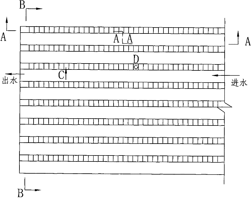
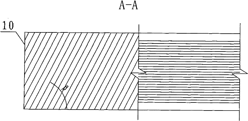
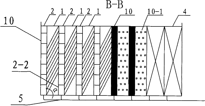
[0008] Specific implementation mode one: as Figure 1~6 As shown, the sloping plate sedimentation tank of the side swirl mud discharge described in this embodiment includes a tank body 10, a plurality of sloping plate sedimentation units 1 and a plurality of sloping plate sedimentation units 2, and a plurality of sloping plate sedimentation units 1 and multiple sloping plate sedimentation units. Two inclined plate mud guide units 2 are arranged in parallel in the tank body 10, and each inclined plate sedimentation unit 1 includes several sedimentation plates 1-1, and the several sedimentation plates 1-1 are inclined in parallel at a certain interval from top to bottom. The inclination angle α of each sedimentation plate 1-1 relative to the horizontal plane is 50°~70°, and each sedimentation plate 1-1 is perpendicular to the two sides of the pool body 10; The inclined plate mud guide unit 2 includes several mud guide plates 2-1 and baffle plates 2-2, and several mud guide plate...

specific Embodiment approach 2

[0009] Specific implementation mode two: as Figure 1~6 As shown, the distance between two adjacent precipitation plates 1 - 1 in this embodiment is 20-450 mm. The turbidity of the effluent from the sedimentation tank can reach 0.8-3NTU. Other components and connections are the same as those in the first embodiment.

specific Embodiment approach 3

[0010] Specific implementation mode three: as Figure 1~6 As shown, the distance between two adjacent mud deflectors 2 - 1 in this embodiment is 5-150 mm. The turbidity of the effluent from the sedimentation tank can reach 0.8-2NTU. Other components and connections are the same as those in the first embodiment.


PUM


Abstract

The invention provides a sloping plate sedimentation tank for lateral rotational flow sludge discharge, relating to a sedimentation tank. The invention solves the problem of poor sludge discharge effects of the existing sloping plate sedimentation tanks. A plurality of sedimentation plates are slantwise arranged in parallel in a tank body at a certain interval from top to bottom, wherein the angleof inclination alpha of each sedimentation plate corresponding to the horizontal plane ranges from 50 degrees to 70 degrees, and each sedimentation plate is perpendicular to tank walls on both sidesof the tank body; a plurality of sludge guide plates are slantwise arranged in parallel in the tank body at a certain interval from top to bottom, the angle of inclination beta of each sludge guide plate corresponding to the horizontal plane ranges from 45 degrees to 90 degrees, each sludge guide plate is perpendicular to the front tank wall and the rear tank wall of the tank body, and baffle plates are arranged on one sides of the plurality of sludge guide plates and are vertically connected with the sludge guide plates; and other sides of the sludge guide plates are connected with the lowerends of the sedimentation plates. Large and small floccule bodies formed on adjacent sloping plate sedimentation units by sedimentation flow into a corresponding trough-like passage along the inclinedsedimentation plates, and the lateral flow speed of water currents is utilized to cause the large floccule bodies to rotationally flow downwards, thereby greatly enhancing the effect of sludge discharge.

Description

technical field [0001] The invention relates to a sedimentation tank. Background technique [0002] The advection sedimentation tank is a rectangular pool. Water flows in from one end and flows out from the other end. The water flows slowly in the pool at a small flow rate, and the particulate impurities in the water will settle down, so as to achieve the purpose of removing particulate impurities in the water. The flocs settle in the laminar flow state. According to the Stokes formula, the settling velocity is proportional to the particle size. The large flocs settle quickly, and the small flocs settle slowly. distribution; and due to the influence of temperature and density, the hyperpycnal flow submerges into the lower part of the pool to flow, resulting in a distribution of flow velocity that is small at the top and large at the bottom. The small flocs in the upper part have low actual surface load because the flow velocity is too small, and the large flocs in the lower...

Claims


Application Information

Patent Timeline
Patent Type & Authority Patents(China)
IPC IPC(8): B01D21/02
Inventor 马军刘增贺
Owner HARBIN INST OF TECH
Why Eureka
Try Eureka