Combination stiffening filling pile

A technology of pouring piles and plain concrete piles, which is applied in the field of geotechnical engineering, can solve the problems of low bending resistance and shear resistance, achieve good economic and environmental benefits, improve the utilization rate of steel materials, and avoid sudden accidents

Active Publication Date: 2009-11-04
ANHUI URBAN CONSTR DESIGN & RES INST
View PDF4 Cites 8 Cited by
  • Summary
  • Abstract
  • Description
  • Claims
  • Application Information

AI Technical Summary

Problems solved by technology

However, this type of pile only has a section steel skeleton in the pile body. Considering the limitation of the arrangement of section steel in a circular section, it is only suitable for a section with a pile diameter of 300mm-600mm, so the bending and shearing resistance is still low. It must be used in combination with prestressed anchor rods, that is, in pile-anchor systems. It is generally difficult to use cantilever alone, and the maximum applicable foundation pit depth does not exceed 15 meters, and the pile length does not exceed 20 meters, which still has great limitations.

Method used


Image

  • Combination stiffening filling pile
  • Combination stiffening filling pile
  • Combination stiffening filling pile

Examples


Embodiment 1

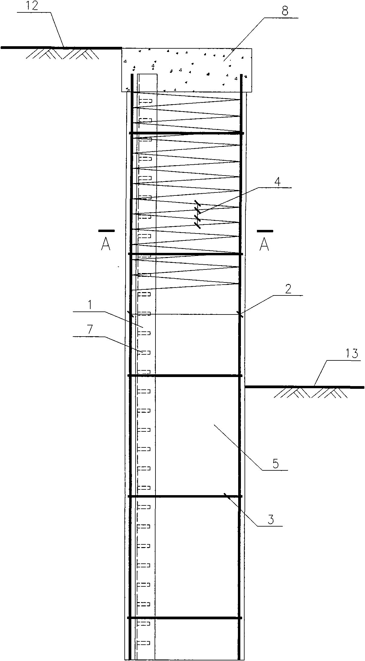
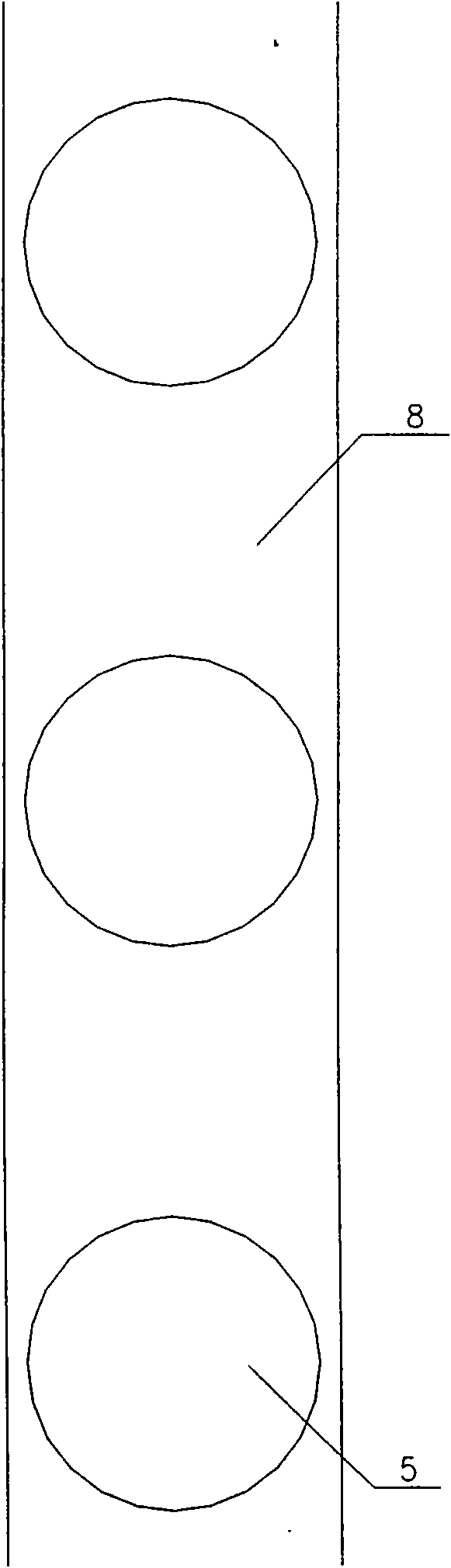
[0041] see figure 1 with Figure 8 , the composite stiffened cast-in-situ pile includes a plain concrete pile body 5, a steel cage and a steel skeleton, and the steel skeleton is coaxial with the plain concrete pile body, and the plain concrete pile body is wrapped with a steel cage and a steel skeleton, and the steel skeleton includes one or two parallel channel steel, see Figure 10 , the reinforcement cage includes stressed longitudinal reinforcement 2 evenly distributed on the circumference, annular reinforcing reinforcement 3 and spiral stirrup 4 surrounding the longitudinal reinforcement;

[0042] The strength of the plain concrete pile body is C20-C30, and different materials can also be selected according to the force of the pile and the diameter of the pile.

[0043] The channel steel model is adjusted according to the calculated bending moment. Various types of ordinary channel steel and light channel steel can be selected, and these steel profiles can also be used...

Embodiment 2

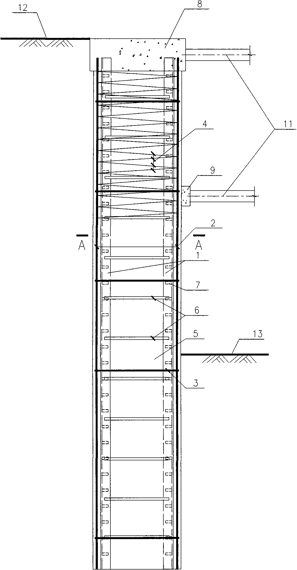
[0050] The profile steel skeleton includes one or two pairs of skeletons composed of two symmetrically arranged channel steels or I-beams, see Figure 7 , Figure 9 with Figure 15 .

[0051] The type of channel steel or I-beam is adjusted according to the calculated bending moment. Various types of ordinary channel steel, light channel steel and I-beam can be selected, and these steel sections can also be used to form a lattice composite section steel.

[0052] Others are with embodiment 1.

Embodiment 3

[0054] see Figure 11 , Figure 13 with Figure 16 , each pair of channel steels or I-beams is radially arranged with horizontal connecting ribs 6 from top to bottom, and the distance between adjacent horizontal connecting ribs 6 is 500-1000 mm.

[0055] When two section steels are symmetrically placed on both sides of the neutral axis of the pile, threaded steel bars or steel plates are used as connecting bars, which are respectively welded to the section steels on both sides to form a lattice-type combined section steel; the vertical distance is 500-1000 mm, according to the groove Adjust the steel layout accordingly.

[0056] Others are with embodiment 1.


PUM


Abstract

The invention relates to a cantilever type piling supporting structure and a combination stiffening filling pile in a branch anchor type piling supporting structure. The combination stiffening filling pile comprises a plain concrete pile shaft, a reinforcing cage, a profile steel skeleton which is coaxial with the plain concrete pile shaft wrapping up the reinforcing cage and the profile steel skeleton; the profile steel skeleton comprises more than one channel steels or I-beams; the reinforcing cage comprises longitudinal bars uniformly distributed on the circumference, ring-shaped reinforcing ribs and tie hoops encircling the longitudinal bars; the diameter of the plain concrete pile shaft is 400 to 1200 mm; and the pile length is 5-25 meters; more than one channel steels or the I-beams and the longitudinal bars of the reinforcing cage are positioned inside a tensile region of the same circumference or in the interior of the reinforcing cage; the channel steels or the I-beam ventral shields are uniformly distributed with shear keys from top to bottom.

Description

technical field [0001] The invention belongs to the field of geotechnical engineering, and in particular relates to a combined stiffened cast-in-situ pile in a cantilever type pile row support structure and an anchor type pile row support structure. Background technique [0002] At present, the column-type soil retaining piles used in the foundation pit enclosure in China are mainly mechanically drilled or artificially drilled reinforced concrete pouring piles, which are circular in shape and 400-1200 mm in diameter. Longitudinal bars with a force of more than 1 mm and structural steel bars form a circular steel cage, whose diameter is smaller than the pile diameter, leaving 40-50 mm outside as a protective layer. There are several forms of section reinforcement: [0003] Cantilever type, due to the one-sided earth pressure, the tension zone only exists on the side facing the soil, and most of the longitudinal reinforcement is concentrated in the tension zone, while the oth...

Claims


Application Information

Patent Timeline
Patent Type & Authority Applications(China)
IPC IPC(8): E02D5/34E02D17/20
Inventor 束冬青李彪蔡敏
Owner ANHUI URBAN CONSTR DESIGN & RES INST
Why Eureka
Try Eureka