Photoresist removing machine station and photoresist removing process

A technology of photoresist and process, which is applied in the field of photoresist removal process, can solve problems such as wafer 20 photoresist bursting, and achieve the effect of improving process pass rate and avoiding bursting

Inactive Publication Date: 2009-11-04
TAIWAN SEMICON MFG CO LTD
View PDF0 Cites 1 Cited by
  • Summary
  • Abstract
  • Description
  • Claims
  • Application Information

AI Technical Summary

Problems solved by technology

After the wafer 20 enters the photoresist removal machine 10, the heater 12 begins to heat up under the influence of the temperature controller 14. Since the process time must be shortened as much as possible, the heater 12 will heat up rapidly. Tool 11 will move vertically, and wafer 20 will move to process position (such as Figure 1B position shown), because the wafer carrier 11 in the traditional photoresist removal machine 10 can only make the wafer 20 stay at the carrying position and the process position, and the rapid temperature rise will easily cause the photoresist The temperature in the removal machine 10 is higher than the process temperature, so when the wafer 20 is heated at a high temperature, the distance between the wafer carrier 11 and the heater 12 is too close, and the photoresist burst (photoresistance) of the wafer 20 may occur. popping)

Method used


Image

  • Photoresist removing machine station and photoresist removing process
  • Photoresist removing machine station and photoresist removing process
  • Photoresist removing machine station and photoresist removing process

Examples


Embodiment Construction

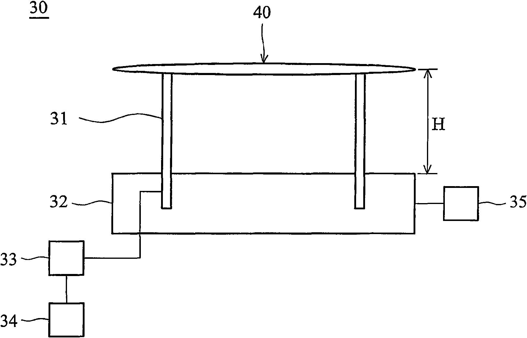
[0038] see Figure 2A-Figure 2C , Figure 2A It is a schematic diagram showing that the wafer carrier of the photoresist removal machine of the present invention is located at the carrying position, Figure 2B It is a schematic diagram that the wafer carrier of the photoresist removal machine of the present invention is located at the cooling position, and Figure 2C It is a schematic diagram of the wafer carrier located in the process position of the photoresist removal tool of the present invention. The photoresist removing machine 30 of the present invention is used to remove the photoresist on the wafer 40 , and includes a wafer carrier 31 , a heater 32 , a motor 33 , a height control unit 34 and a temperature controller 35 . The wafer carrier 31 supports the wafer 40 and makes the wafer 40 vertically displace relative to the heater 32. The motor 33 is electrically connected to the wafer carrier 31, and the height control unit 34 is electrically connected to the motor 33...


PUM


Abstract

The invention provides a photoresist removing machine station and a photoresist removing process. The photoresist removing machine station comprises a heater, a wafer carrier, a motor and a height control unit, wherein the wafer carrier is provided for a wafer to make vertical displacement relative to the heater; the motor is electrically connected with the wafer carrier and the height control unit respectively; and the height control unit is used for controlling the wafer to stop on at least three positions. The photoreist removing process comprises the following steps: positioning the wafer at a bearing position by utilizing the wafer carrier when the wafer enters the photoresist removing machine station; moving the wafer carrier to move the wafer to a temperature-reduction position; and moving the wafer carrier to move the wafer to a process position. The invention can avoid cracking of photoresist caused by overheating of the wafer, thereby improving the qualification rate.

Description

technical field [0001] The invention relates to a photoresist removal machine and a photoresist removal process. Background technique [0002] see Figure 1A , Figure 1B , Figure 1A It is a schematic diagram of the wafer carrier of the traditional photoresist removal machine in the loading position, while Figure 1B A schematic diagram of the wafer carrier at the process position of a conventional photoresist removal tool. The photoresist removal machine 10 is used to remove the photoresist on the wafer 20. The traditional photoresist removal machine 10 includes a wafer carrier 11, a heater 12, a motor 13 and a temperature controller 14. When the wafer 20 enters the photoresist removal machine 10, the wafer 20 is positioned at the carrying position (such as Figure 1A The position shown), at this time, the distance between the wafer 20 and the heater 12 is 2 mm, so that the wafer 20 is transferred from the external machine (not shown in the figure) to the photoresist rem...

Claims


Application Information

Patent Timeline
Patent Type & Authority Applications(China)
IPC IPC(8): G03F7/42
Inventor 吴瑞鸿方建章张凤如杨思宏萧士杰
Owner TAIWAN SEMICON MFG CO LTD
Why Eureka
Try Eureka