

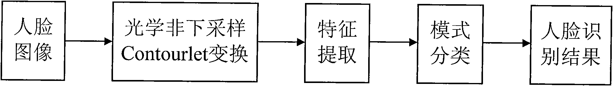
Face recognition method based on optics nonsubsampled Contourlet conversion
A non-subsampling contour and non-subsampling technology, applied in the field of pattern recognition, can solve problems such as difficult to meet real-time face recognition and slow recognition speed
- Summary
- Abstract
- Description
- Claims
- Application Information
AI Technical Summary
Problems solved by technology
Method used
Image

Examples
Embodiment 1
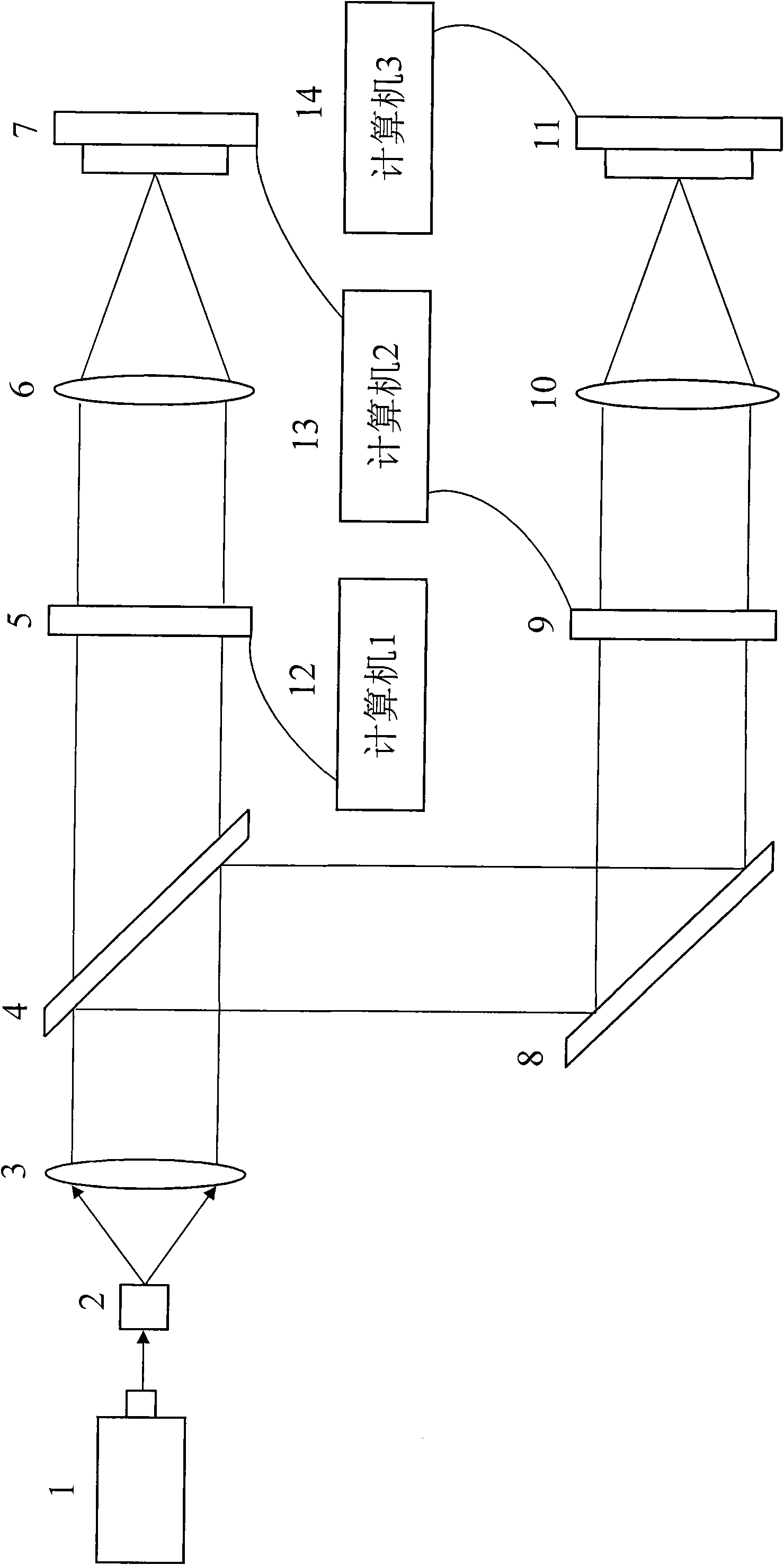
[0046] Embodiment 1: the structure of the optical non-subsampling Contourlet transformation module is as follows figure 2 As shown, the helium-neon laser 1 is located at 18 cm ahead of the pinhole filter 2, the pinhole filter 2 is located at the front focal plane of the collimator lens 3, and a beam splitter 4 is installed at 18 cm behind the collimator lens 3, and the beam splitter 4 rear Install the first electrical addressing spatial light modulator 5 at 28 cm, the electrical addressing spatial light modulator 5 is located at the front focal plane of the first Fourier lens 6, and the first Fourier lens 6 is installed at the rear focal plane A CCD optocoupler device 7; a plane reflector 8 is installed at 28 cm below the beam splitter 4, and a second electric addressing spatial light modulator 9 is installed at a place 28 cm behind the plane reflector, and the electric addressing spatial light modulator 9 is located at the second Fu At the front focal plane of the Liye lens ...
Embodiment 2
[0055] Embodiment 2 has the same structure and method as Embodiment 1, but the difference is that in Embodiment 2, the helium-neon laser 1 is positioned at 16 cm in front of the pinhole filter 2, and a beam splitter 4 is installed at 16 cm behind the collimating lens 3, and the beam splitter 4 A first electrical addressing spatial light modulator 5 is installed at the rear 26 cm, a plane reflector 8 is installed at 26 cm below the beam splitter 4, a second electrical addressing spatial light modulator 9 is installed at 26 cm behind the plane mirror 8, and the beam splitter The beam splitting angle is 50 degrees.
Embodiment 3
[0056] Embodiment 3 has the same structure and method as Embodiment 1, except that in Embodiment 3, the helium-neon laser 1 is positioned at 20 cm in front of the pinhole filter 2, and a beam splitter 4 is installed at 20 cm behind the collimating lens 3, and the beam splitter 4 The first electrical addressing spatial light modulator 5 is installed at the rear 30 cm, the plane reflector 8 is installed at 30 cm below the beam splitter 4, the second electrical addressing spatial light modulator 9 is installed at the rear 30 cm of the plane mirror 8, and the beam splitter The beam splitting angle is 70 degrees.
[0057] Apply the optical non-subsampling Contourlet transformation module to realize the non-subsampling Contourlet transformation of the face image, such as figure 2 As shown, a helium-neon laser 1 passes through a pinhole filter 2 and a collimating lens 3 to form parallel light, transmits it on a first electrical addressable spatial light modulator 5 through a beam sp...
PUM
 Abstract
Description
Claims
Application Information