Vibratory transducer

A measurement transducer, vibration-type technology, applied in the direction of measuring device, measuring capacity, mass flow measuring device, etc.

Active Publication Date: 2009-11-04
ENDRESS HAUSER FLOWTEC AG
View PDF25 Cites 0 Cited by
  • Summary
  • Abstract
  • Description
  • Claims
  • Application Information

AI Technical Summary

Problems solved by technology

Unfortunately, however, it has also been found that the aforementioned zero-point errors deviate from the ideal central position by very small amounts, deviations in particular of the order of tolerances that can be assumed by manufacturing and/or assembly technology, and that t

Method used


Image

  • Vibratory transducer
  • Vibratory transducer
  • Vibratory transducer

Examples


Embodiment Construction

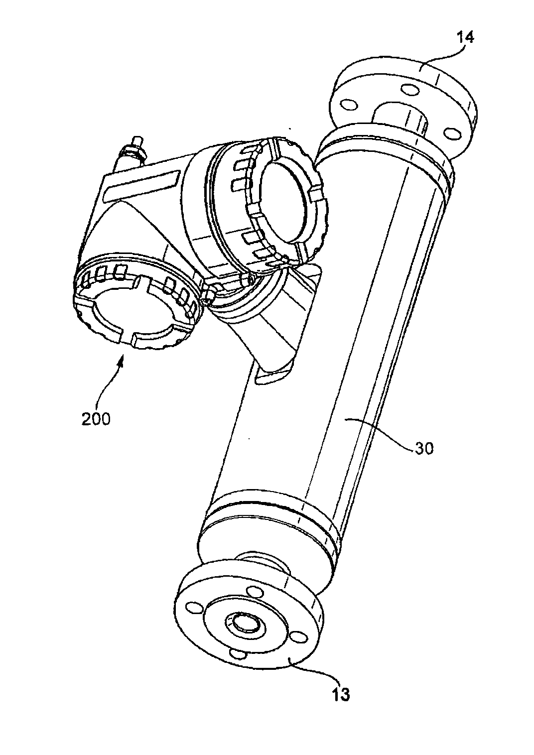
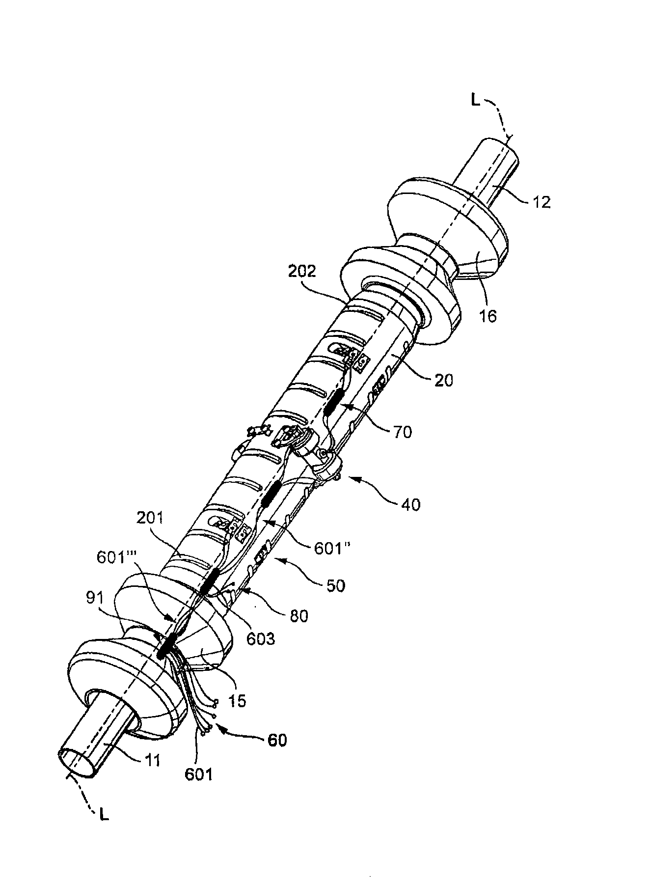
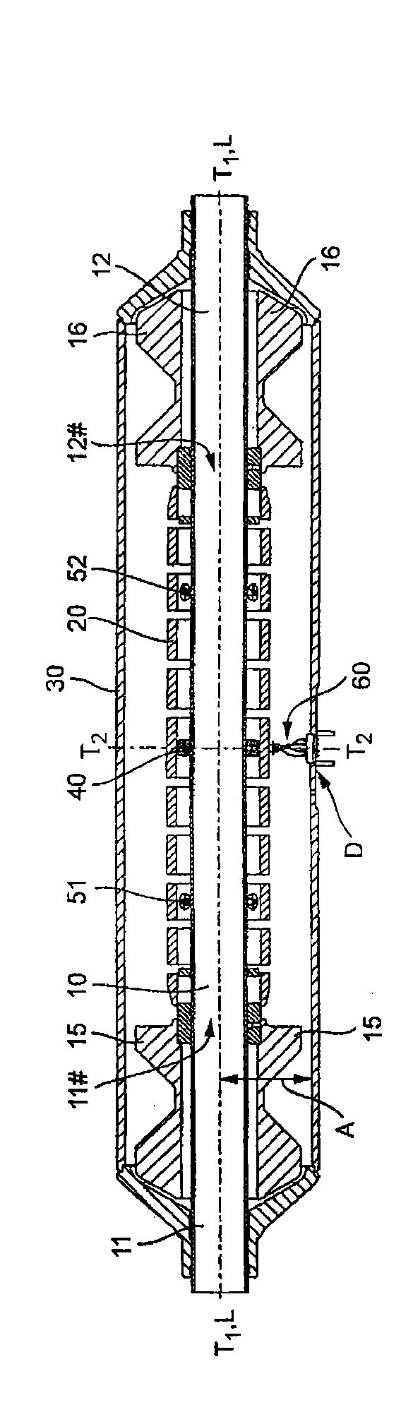
[0061] figure 1 Shown is an in-line measuring instrument that can be inserted into a pipeline not shown here, such as a Criolis mass flow meter, a density meter, a viscometer, etc., for measuring and / or monitoring at least one parameter of a medium flowing in the pipeline , such as mass flow, density, viscosity, etc. The in-line measuring instrument comprises for this purpose a vibrating measuring transducer, through which the medium to be measured flows during operation, the measuring transducer being electrically connected to operating and analyzing electronics, not shown here, of the in-line measuring instrument, which operating and analyzing Electronics are housed in corresponding electronics housings 200 . Figure 2-5 A corresponding embodiment and configuration of such an oscillating measuring transducer is shown schematically. Otherwise, the main mechanical structure and its mode of operation are similar to the measuring transducers disclosed in US-B 66 91 583 or US-B...


PUM


Abstract

The invention relates to a transducer comprising a measuring tube (10) which vibrates at least intermittently during operation and is used to guide the medium, said measuring tube (10) communicating with the tubular conduit by means of an inlet tube piece (11) opening up on the inlet side and an outlet tube piece (12) opening up on the outlet side; a counter vibrator (20) which is fixed to the measuring tube on the inlet side and on the outlet side, forming coupling regions (11#, 12#); a bracket (15) coupled to the measuring tube (10) on the inlet side; a bracket (16) coupled to the measuringtube (10) on the outlet side; a sensor arrangement (50) held on the couter vibrator at least in parts and used to detect vibrations at least of the measuring tube (10); an exciter arrangement (40) held on the counter vibrator (20) at least in parts and used to drive at least the measuring tube (10); a transducer housing (30) fixed to the inlet tube piece (11) and to the outlet tube piece (12); andconnection lines of which one is held at least at certain points on an inner part formed by the measuring tube, the counter vibrator and the two brackets, and at least at certain points on the transducer housing. A section of at least said connection line extends in a freely vibrating manner between two anchoring points located at a distance from each other. One of the anchoring points is arranged on the inner part of the transducer and another anchoring point is arranged on the transducer housing, such that the relative distance between the same remains essentially unchanged even when the measuring tube vibrates.

Description

technical field [0001] The invention relates to a vibrating measuring transducer, in particular to a vibrating measuring transducer suitable for Creole mass flow meters. Background technique [0002] In order to determine parameters (such as mass flow, density, viscosity, etc. The measuring transducer and the control and evaluation electronics connected thereto induce forces (for example Criolis forces) in the flow medium and generate a measurement signal suitably representing at least one parameter from these forces. Such online measuring devices with vibrating measuring transducers have long been known and are used in industrial applications. Thus, for example in EP-A 317 340, US-A 53 98 554, US-A 54 76 013, US-A 55 31126, US-A 56 91 485, US-A 57 05 754, US-A 57 96 012 , US-A 59 45 609, US-A 59 79 246, US-A 60 06 609, US-B 63 97 685, US-B 66 91 583, US-B 68 40 109, WO-A 99 51 946, Creiolis mass flow meters are described in WO-A 99 40 394 or WO-A 00 14 485, each having a...

Claims


Application Information

Patent Timeline
IPC IPC(8): G01F1/84
CPCG01F15/024G01F1/8418G01F1/8427G01F15/14G01F1/8422G01F1/8409G01F1/849G01F1/8413
Inventor 迈克尔·富克斯莱昂哈德·普罗布斯特阿尔弗雷德·里德迈克尔·维斯曼
Owner ENDRESS HAUSER FLOWTEC AG
Why Eureka
Try Eureka