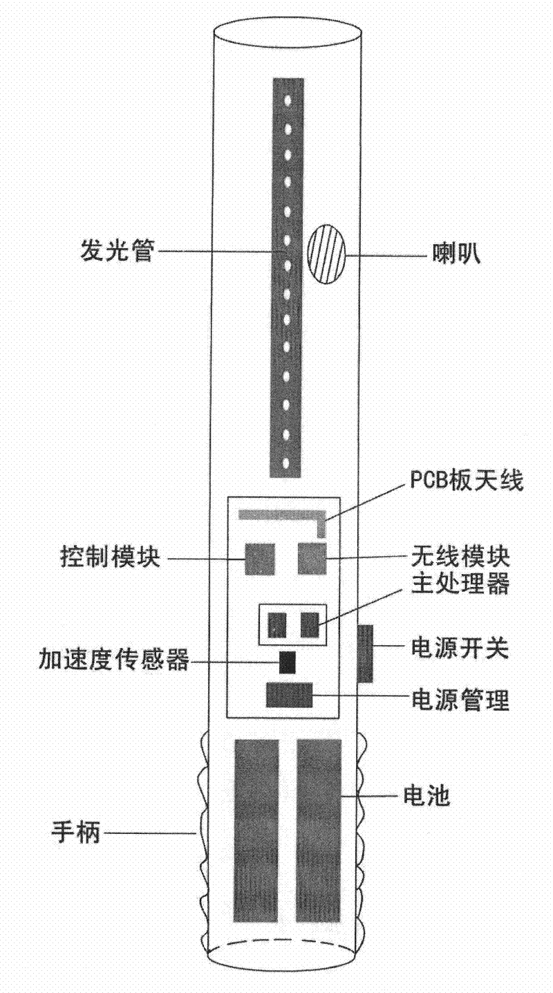
Intelligent refueling rod
An intelligent technology, applied in the transmission system, musical toys, instruments, etc., can solve the problems of not having the interactive function of the control center, affecting the enthusiasm of the audience to participate in the show, and being unable to select the show, etc. achieve the effect of increasing enthusiasm
- Summary
- Abstract
- Description
- Claims
- Application Information
AI Technical Summary
Problems solved by technology
Method used
Image
Examples
Embodiment 1
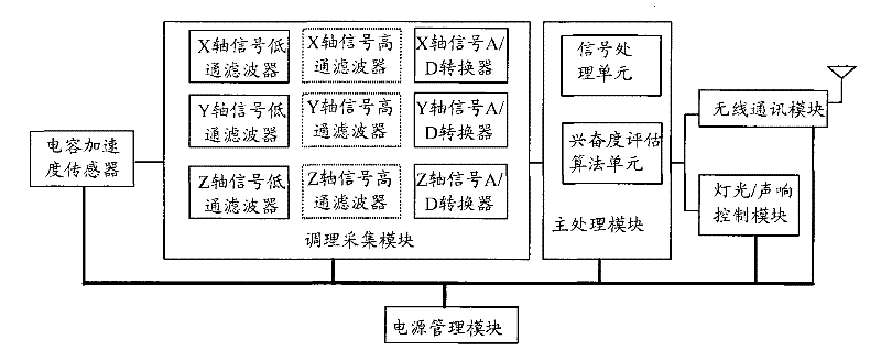
[0087] figure 2 For the first structural schematic diagram of the intelligent fueling rod of the present invention, see figure 2 , the smart refueling stick includes: a refueling stick body, a capacitive acceleration sensor, a conditioning acquisition module, a main processing module, a wireless communication module, a light / sound control module and a power management module, wherein,
[0088] The capacitive acceleration sensor is fixed on the refueling rod body, and is used to sense the acceleration information of the smart refueling rod body, and output the collected analog acceleration information to the conditioning acquisition module;
[0089] In practical applications, the capacitive acceleration sensor can start to collect the acceleration information of the smart fueling rod body when the smart fueling rod is powered on, and sense the acceleration of the fueling rod body in the X-axis, Y-axis, and Z-axis directions; it can also be In order to reduce power consumptio...
Embodiment 2
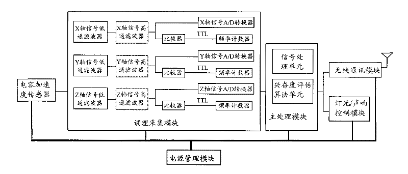
[0109] image 3 It is a schematic diagram of the second structure of the intelligent refueling rod of the present invention, see image 3, the smart refueling stick includes: a refueling stick body, a capacitive acceleration sensor, a conditioning acquisition module, a main processing module, a wireless communication module, a light / sound control module, and a power management module, wherein the refueling stick body, a capacitive acceleration sensor, and a main processing module , wireless communication module, light / sound control module and power management module and figure 2 The structure and function of the corresponding modules are the same, and the low-pass filter and high-pass filter in the conditioning acquisition module are also the same as figure 2 The structure and function of the corresponding modules in the conditioning acquisition module are the same as those of figure 2 The difference is that in this embodiment, each high-pass filter in the conditioning ac...
Embodiment 3
[0115] Figure 4 For the embodiment of the present invention figure 1 and figure 2 The structure diagram of the main processing module shown in , see Figure 4 , the main processing module includes: a signal processing unit and an excitement evaluation algorithm unit, wherein the signal processing unit includes an acceleration amplitude calculation subunit, an acceleration amplitude square and root sign calculation subunit, an acceleration frequency calculation subunit, and an acceleration frequency calculation subunit. Main frequency search algorithm subunit, wherein,
[0116] The acceleration amplitude calculation sub-unit is used to receive the sampled digital signal output by the conditioning acquisition module, and to perform the sampled digital signal on the X-axis, Y-axis, and Z-axis within the preset time length for participating in the evaluation score of excitement. The peak-to-peak calculation obtains the maximum peak-to-peak value of each axis respectively;
...
PUM
 Abstract
Description
Claims
Application Information
 - R&D
- Intellectual Property
- Life Sciences
- Materials
- Tech Scout
- Unparalleled Data Quality
- Higher Quality Content
- 60% Fewer Hallucinations
Browse by: Latest US Patents, China's latest patents, Technical Efficacy Thesaurus, Application Domain, Technology Topic, Popular Technical Reports.
© 2025 PatSnap. All rights reserved.Legal|Privacy policy|Modern Slavery Act Transparency Statement|Sitemap|About US| Contact US: help@patsnap.com


