Hydraulic valve control device and method for checking a hydraulic valve control device

A technology for controlling equipment and hydraulic valves, applied in mechanical equipment, general control systems, electrical program control, etc.

Inactive Publication Date: 2009-11-11
ROBERT BOSCH GMBH
View PDF4 Cites 4 Cited by
  • Summary
  • Abstract
  • Description
  • Claims
  • Application Information

AI Technical Summary

Problems solved by technology

But the problem is that the construction elements used for the safety circuit breaker are also subject to aging processes, and in the event of failure of the central safety circuit breaker, the system controlled by the hydraulic valve may react undesirably

Method used


Image

  • Hydraulic valve control device and method for checking a hydraulic valve control device
  • Hydraulic valve control device and method for checking a hydraulic valve control device
  • Hydraulic valve control device and method for checking a hydraulic valve control device

Examples


Embodiment Construction

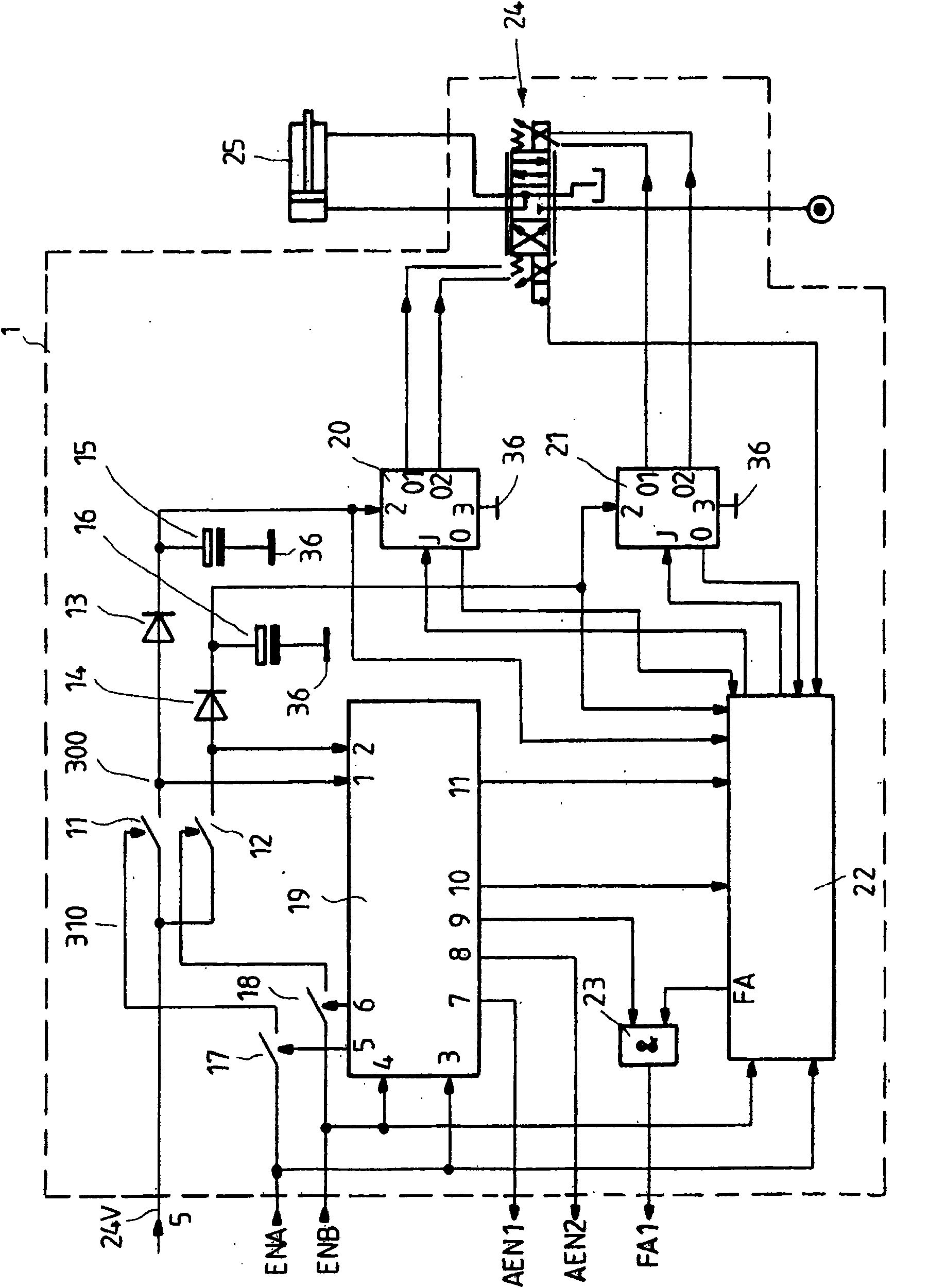
[0067] figure 1 The design of the hydraulic valve control device 1 according to the invention is shown schematically, which has an integrated hydraulic valve 24 . The integration means that the hydraulic valve 24 and the valve electronic device for controlling the hydraulic valve 24 are all installed in one housing together.

[0068] The function of the hydraulic valve 24 is to drive the hydraulic cylinder 25 located outside the casing. The hydraulic valve is designed as a proportional valve in which a magnetic field is generated by means of a coil. This magnetic field moves the spool in the valve according to the current passing through the coil. In other embodiments, other current-driven actuators can also be used instead of coils.

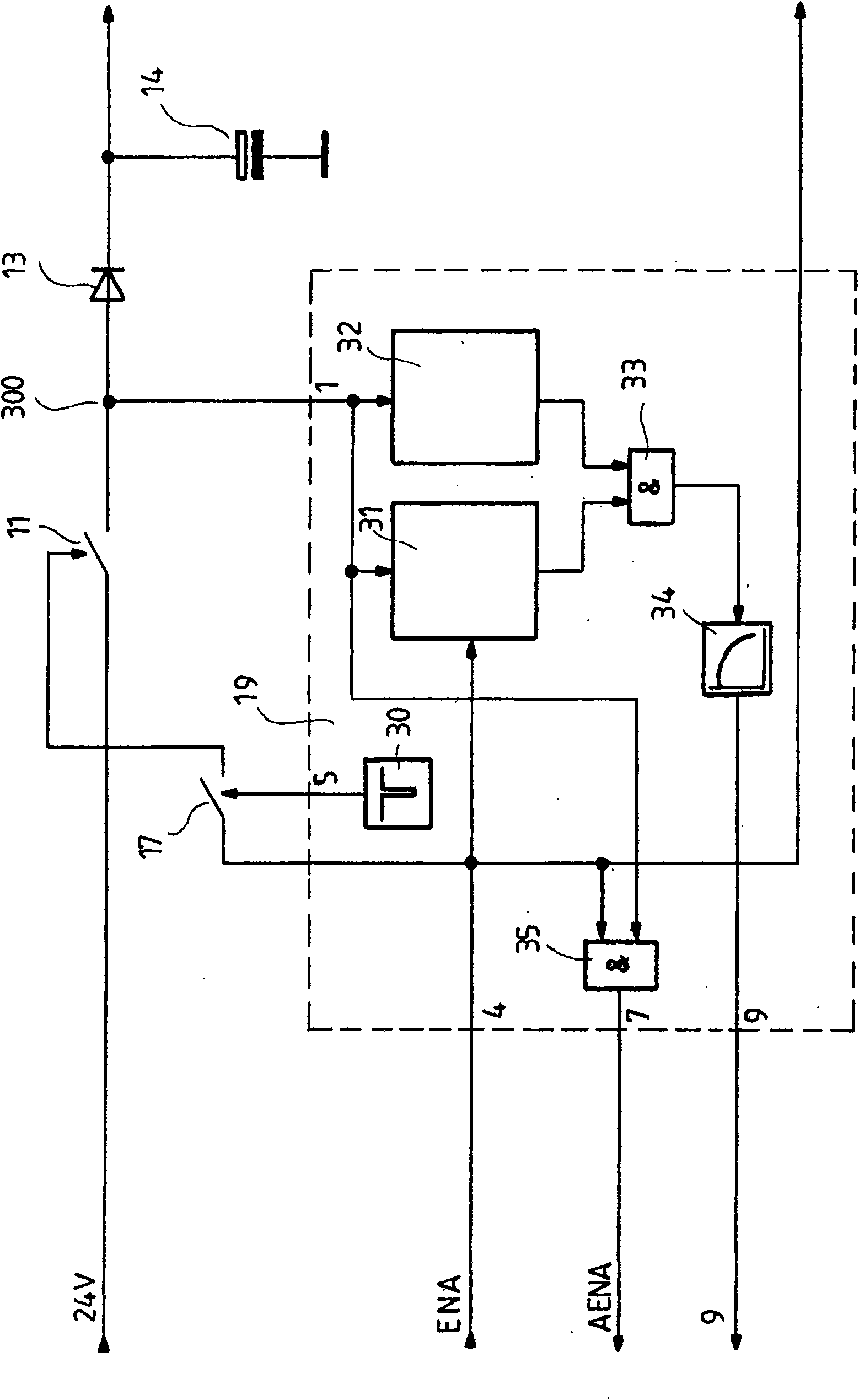
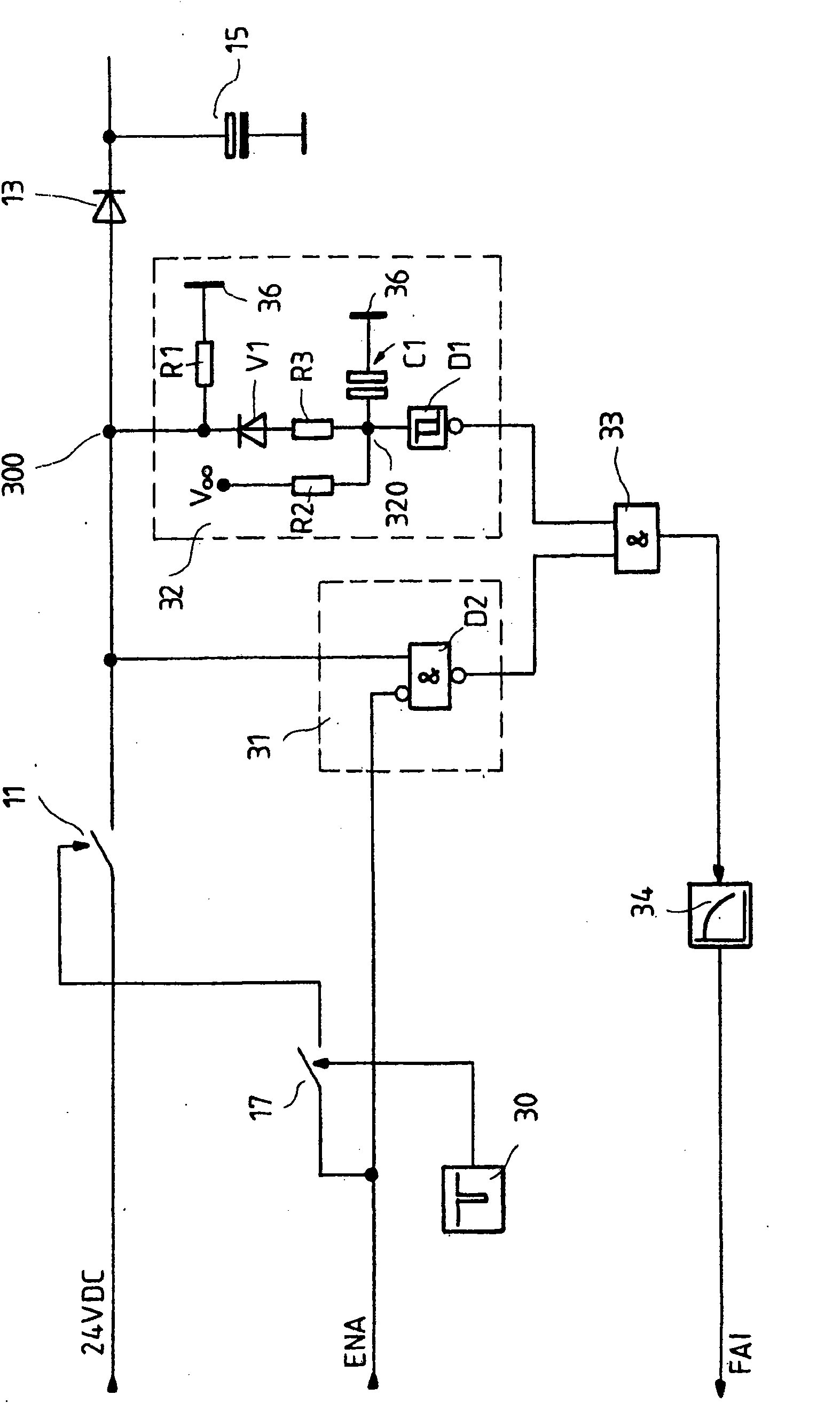
[0069] The hydraulic valve control device 1 comprises a first output stage 20 , a second output stage 21 and an output stage controller 22 . The output stages 20 and 21 each have an input I, two outputs O1 and O2 , a feedback output O, a fir...


PUM


Abstract

The invention provides a hydraulic valve control device for a hydraulic valve containing at least one actuator. The hydraulic valve control device comprises a voltage supply input, an output stage configured to output a drive current for driving the actuator of the hydraulic valve, wherein the output stage has a first voltage supply input. A first switch is disposed between the first voltage supply input of the output stage and a first voltage supply input of the hydraulic valve control device. An enable input is configured to switch the output stage on and off. A switch-off device is configured to open the first switch when the output stage is off. A checking circuit is configured to repeatedly open the first switch when the output stage is on. And a measurement circuit is configured to detect whether the checking circuit opens the first switch.

Description

technical field [0001] The invention relates to a hydraulic valve control device and a method for detecting the hydraulic valve control device. For hydraulic valves, especially for hydraulic valves in working machines, safety measures should be taken so that the hydraulic valve does not cause movements that are harmful to the outside world. For this reason, especially with hydraulic valves having a solenoid coil for moving the spool, care should be taken to reliably avoid unintentional powering of the solenoid coil. [0002] The solenoid coil is driven by the final stage, which is powered by a voltage source. In addition to the disconnection function of the final stage, ie its output is connected with a high resistance when the power supply is switched off, it should also be possible to separate the final stage from the mains voltage by means of a switch as a safety measure. Background technique [0003] In the publication RD 95200 of November 2007 from the company Bosch R...

Claims


Application Information

Patent Timeline
Patent Type & Authority Applications(China)
IPC IPC(8): F15B21/02G05B19/02
CPCF15B20/002F15B19/00G05B9/02
Inventor D·凯勒
Owner ROBERT BOSCH GMBH
Why Eureka
Try Eureka