Method and system for laser detection of shape of charge level

A material surface and laser technology, applied in the direction of measuring devices, optical devices, instruments, etc., can solve the problems of unsatisfactory detection accuracy and achieve the effects of reduced maintenance rate, high accuracy and simple detection method

Inactive Publication Date: 2009-11-11
SHENVANG PAJONIIR TEK CORP BEJDZHING +1
View PDF1 Cites 28 Cited by
  • Summary
  • Abstract
  • Description
  • Claims
  • Application Information

AI Technical Summary

Problems solved by technology

The detection accuracy of this detection method is not satisfactory in some fields. In addition, the accuracy requirements of the system are very strict. In addition, the detection accuracy is also greatly affected by the composition of the object itself.

Method used


Image

  • Method and system for laser detection of shape of charge level
  • Method and system for laser detection of shape of charge level
  • Method and system for laser detection of shape of charge level

Examples


Embodiment Construction

[0015] The system and method for detecting the shape of the material surface using laser lines according to the present invention will be described in detail below by taking the material surface (usually moving) of the sintering machine as an example.

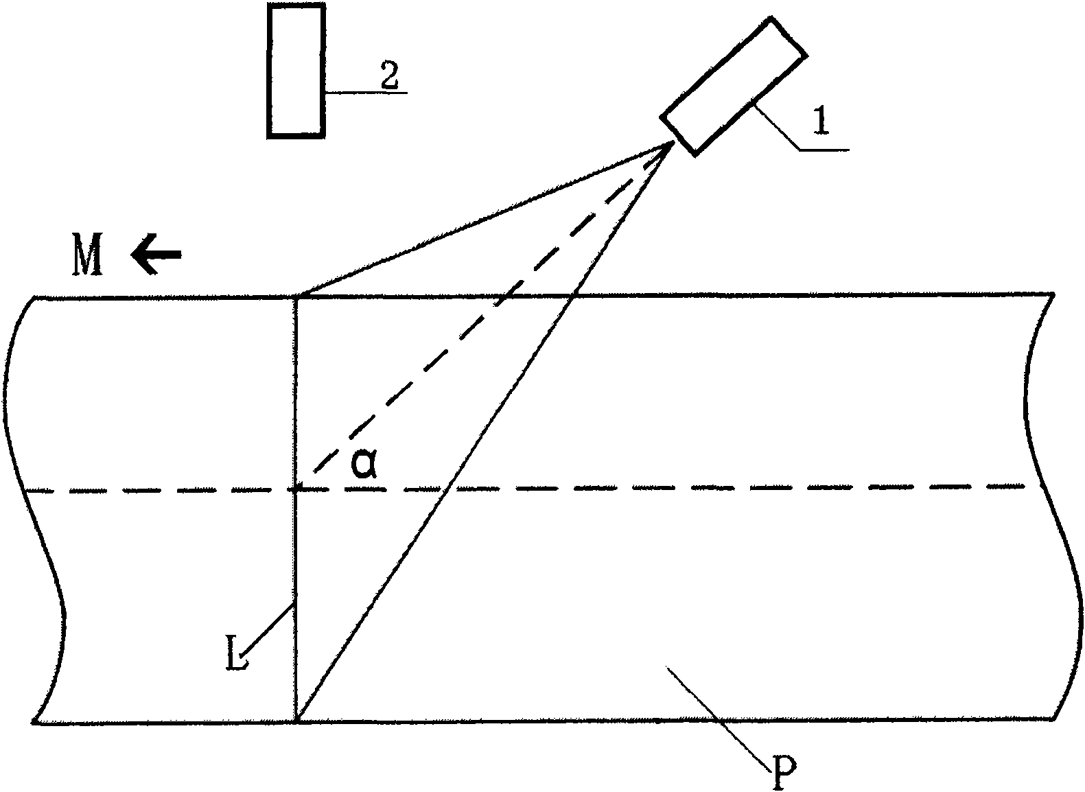
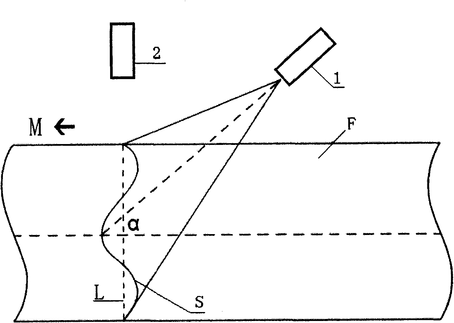
[0016] see figure 2 with image 3 , the reference plane (imaginary horizontal plane) of the material surface of the sintering machine is marked as P. The line laser 1 is positioned above the material surface, and the plane defined by the generated laser beam is parallel to the transverse direction (width direction) of the material surface and forms an angle α with the longitudinal direction M (movement direction or length direction) of the material surface. The included angle α is usually in the range of 10° to 80°, preferably around 45°. The camera 2 is positioned directly above the position (reference line L) where the laser beam generated by the online laser 1 intersects the reference plane (or reference material surface)...


PUM


Abstract

The invention provides a method and a system for laser detection of the shape of charge level. The method comprises the following steps: exerting a laser beam on the charge level to be detected from the upper part of the charge level to be detected, and making the plane limited by the laser beam parallel to the transverse direction (width direction) of the charge level to be detected and angulated at an included angle alpha with the longitudinal direction (movement direction or length direction) of the charge level to be detected; shooting a picture on an intersection line of the laser beam and the charge level directly from the upper part of an intersected position of the laser beam and a reference charge level; and acquiring the shape of the charge level according to the shot image of the intersection line. The method for detecting the charge level is simple and has high precision. Moreover, the system for detecting the charge level does not need to directly contact the charge level, so that the maintenance rate of the system is greatly reduced.

Description

technical field [0001] The present invention relates to the detection of the shape of a material surface, and more particularly, to a method and a system for detecting the shape of a material surface, such as a sintering machine, using a laser. Background technique [0002] Such as figure 1 As shown, the traditional sintering machine material level detection system includes two adjacent detection heads 5 and 6 arranged side by side above the material surface F. The heights of the two detection heads are different. Lower altitude. When the upper limit height detection head 5 detects the material, it indicates that the material level is too high; when the lower limit height detection head 6 does not detect the material, it indicates that the material level is too low. In this kind of material level detection system, since the detection head often needs to be in contact with the material, it is easy to cause the problem of detection head failure. In addition, this detection ...

Claims


Application Information

Patent Timeline
Patent Type & Authority Applications(China)
IPC IPC(8): G01B11/24G01B11/02G01B11/30
Inventor 高征铠萧嘉贤赵承平简荣村高永刘春晖高泰刘哲生
Owner SHENVANG PAJONIIR TEK CORP BEJDZHING
Why Eureka
Try Eureka