
Carabiner with rubber sleeve

A technology of shackles and components, which is applied in the field of shackles and can solve the problems of not teaching anti-slip devices

Inactive Publication Date: 2009-11-11
DAVID L ABELS
View PDF6 Cites 7 Cited by
  • Summary
  • Abstract
  • Description
  • Claims
  • Application Information

AI Technical Summary

Problems solved by technology

However, the shackle has a tendency to slide from one side to the other on the handle under the weight of the item being hung by the shackle and / or due to movement applied to the item being hung
Although U.S. Patent No. 6,606,769 shows a thick edged fabric around the bottom upright portion of the shackle to prevent slipping of an item attached to the shackle (such as a dog leash), this patent does not teach the use of a shackle on the hook. Use of non-slip devices on the shackle of a cylindrical or tubular handle that is mounted or attached to the handle

Method used


Image

  • Carabiner with rubber sleeve
  • Carabiner with rubber sleeve
  • Carabiner with rubber sleeve

Examples


Embodiment Construction

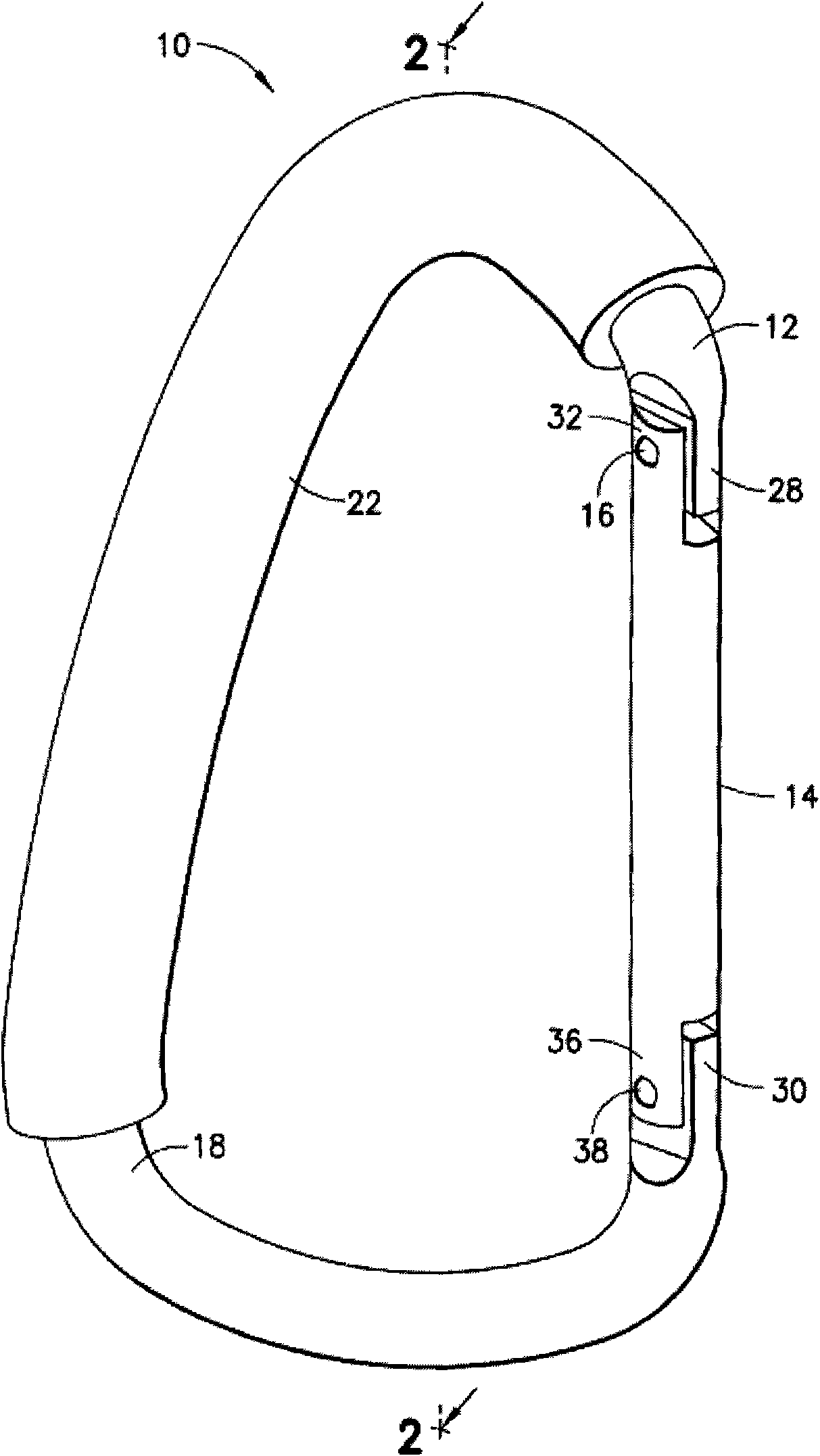
[0017] Referring now in detail to the drawings, wherein like reference numerals represent like parts throughout, figure 1 One embodiment of a shackle 10 of the present invention is shown.

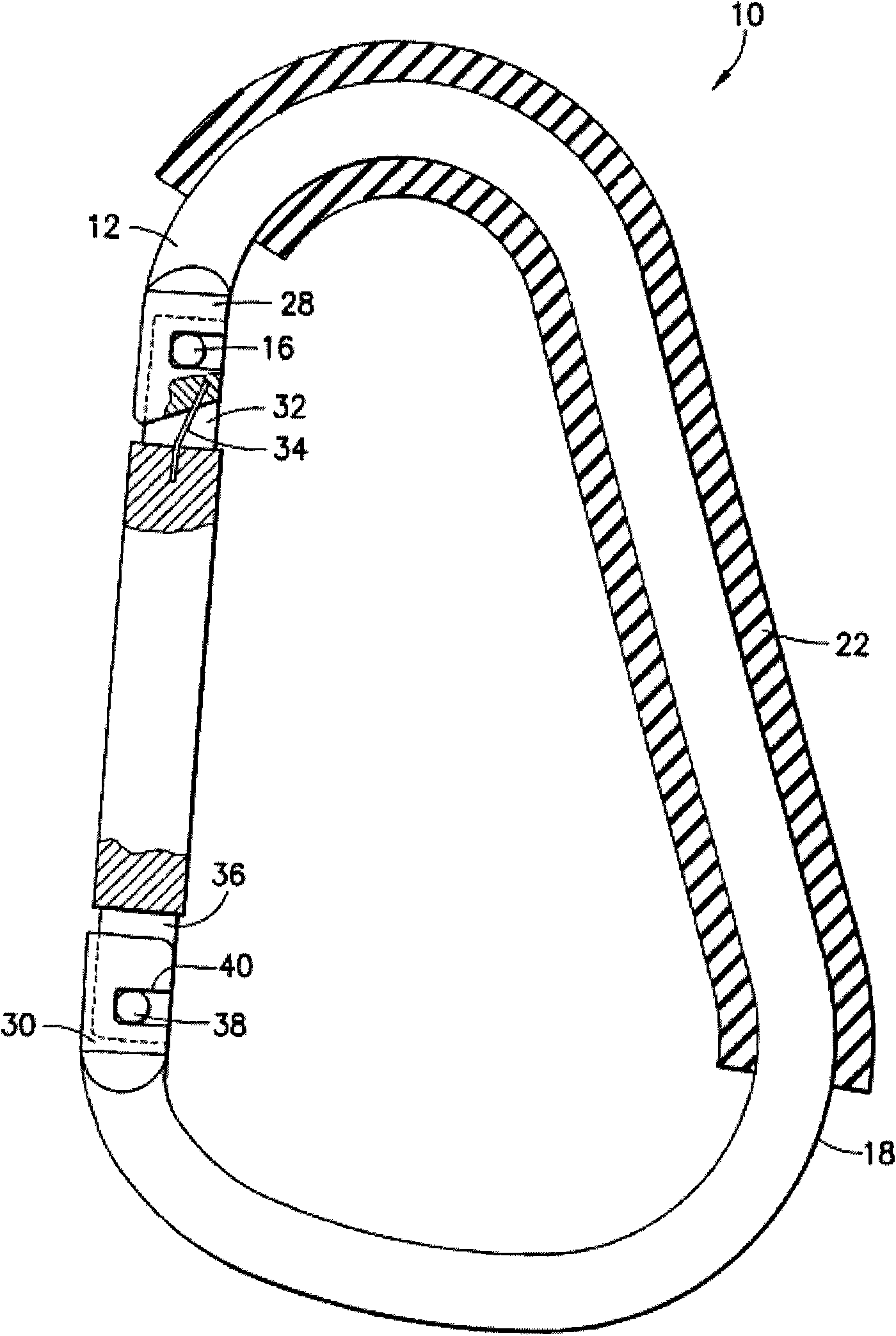
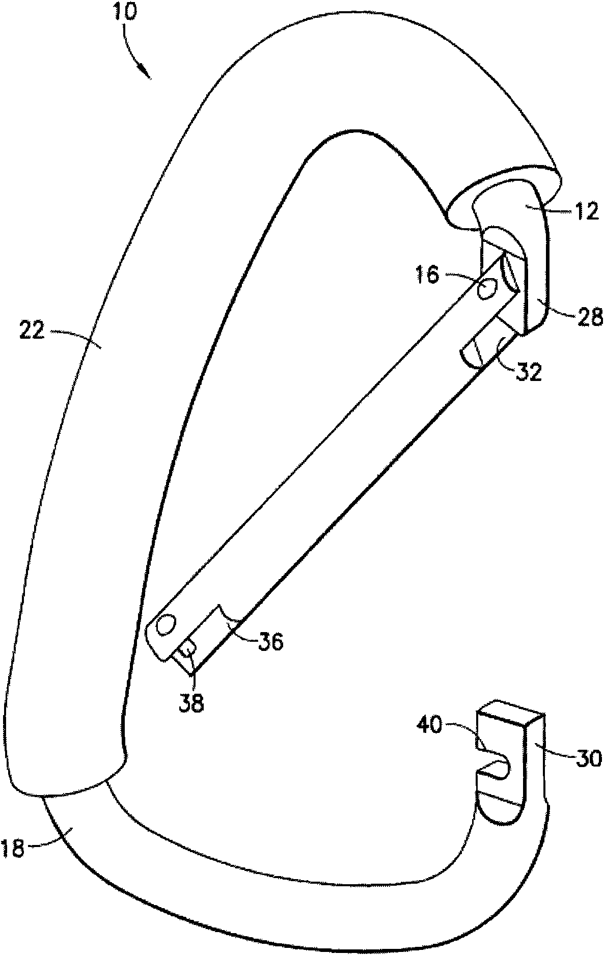
[0018] As shown, the shackle 10 is formed from a substantially C-shaped member 12 and includes a door member 14 that is hinged about a pivot pin 16 . When the door part 14 is located as figure 1 During the closed position shown, except that the upper part of the C-shaped member 12 is formed with a rounded shortened top 18 so that when the shackle 10 is suspended as in Figure 7 The configuration of the C-shaped member 12 and the door member 14 is substantially oval, except that the round handle 20 shown in FIG.

[0019] A rubber sleeve 22 extends around the C-shaped member 12 from a point adjacent to the pivot pin 16 and surrounds at least the top 18 of the member 12, as figure 1 shown in . When the shackle 10 is suspended from the round handle, the sleeve 22 creates sufficient friction...


PUM


Abstract

A carabiner provided with a load bearing apex portion having a rubber sleeve for preventing side-to-side slippage of the carabiner on a rounded handle of a mobile vehicle such as a stroller or shopping cart.

Description

technical field [0001] The present invention relates to a carabiner, and more particularly to a carabiner in the form of a C-shaped structure having a hinged opening which can be opened and closed to form a carabiner for A strong, hook-like hanger or carrier for multiple items. Background technique [0002] Shackles have long been used in rock climbing, for example, for hanging and securing ropes during climbing, such as described in U.S. Patent Nos. 4,095,316; 4,811,467; 5,005,266; 5,329,675; . [0003] More recently, the use of carabiners has expanded to: hanging items (such as key chains) from clothing belts, dogs on leashes, or even on mobile vehicles with cylindrical handles (such as strollers, shopping carts, etc.) Hang packages, diaper bags, camera bags or shopping bags on top. However, the shackle has a tendency to slide from one side to the other on the handle under the weight of the item being hung by the shackle and / or due to movement imparted to the item being...

Claims


Application Information

Patent Timeline
IPC IPC(8): A44B13/00F16B45/02
Inventor 戴维·L·埃布尔斯
Owner DAVID L ABELS
Learn More