Method for manufacturing metal composite plates by stirring friction

A metal composite plate and friction stir technology, which is applied in the direction of manufacturing tools, metal processing equipment, non-electric welding equipment, etc., can solve the problems of narrow application range, complicated process, uneven welding layer surface, etc., achieve smooth surface and wide application range , low cost effect

Inactive Publication Date: 2009-11-18
HARBIN INST OF TECH
View PDF0 Cites 20 Cited by
  • Summary
  • Abstract
  • Description
  • Claims
  • Application Information

AI Technical Summary

Problems solved by technology

[0003] The purpose of the present invention is to solve the problems of uneven welding layer surface, complex process and narrow application range in the existing method for manufacturing metal composite panels, and then provide a method for manufacturing metal composite panels by stirring friction

Method used


Image

  • Method for manufacturing metal composite plates by stirring friction

Examples


specific Embodiment approach 1

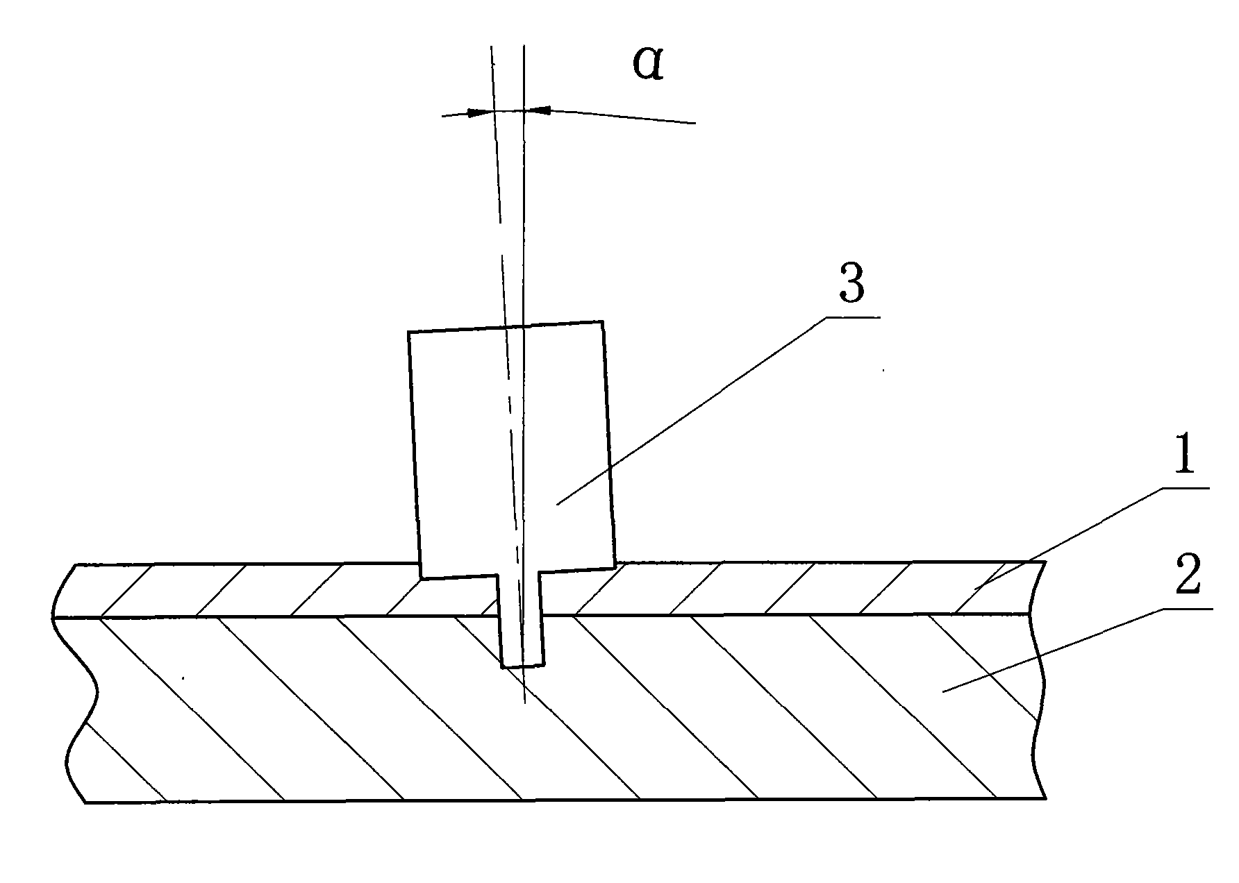
[0010] Specific implementation mode one: as figure 1 As shown, the method for manufacturing metal composite panels by friction stir described in this embodiment is realized according to the following steps:

[0011] Step 1. Place the metal cladding plate 1 on the upper surface of the metal substrate 2, and fix the metal cladding plate 1 and the metal substrate 2 on the workbench. The thickness of the metal cladding plate 1 is 0.3-10 mm, and the thickness of the metal substrate 2 is 0.3 ~ 100mm;

[0012] Step 2, place the stirring head 3 at any position on the upper surface of the metal cladding plate 1, the angle a between the stirring head 3 and the vertical direction is 0-10°, and the stirring head 3 rotates at 200-3000 rpm Pass through the metal cladding plate 1 and penetrate into the metal substrate 2, the speed of the stirring head 3 is 1-5mm / minute, and the depth of penetration into the metal substrate 2 is 0.1mm-100mm;

[0013] Step 3. When the stirring head 3 reaches...

specific Embodiment approach 2

[0015] Specific implementation mode two: as figure 1 As shown, the metal cladding plate 1 described in step 1 of this embodiment is an aluminum plate or an aluminum alloy plate, and the metal substrate 2 is a magnesium plate or a magnesium alloy plate. The material of the composite panel can be selected according to the specific application. Others are the same as in the first embodiment.

specific Embodiment approach 3

[0016] Specific implementation mode three: as figure 1 As shown, the metal cladding plate 1 described in Step 1 of this embodiment is a magnesium plate or a magnesium alloy plate, and the metal substrate 2 is a stainless steel plate. The material of the composite panel can be selected according to the specific application. Others are the same as in the first embodiment.


PUM

PropertyMeasurementUnit
thicknessaaaaaaaaaa
thicknessaaaaaaaaaa
thicknessaaaaaaaaaa

Abstract

The invention discloses a method for manufacturing metal composite plates by stirring friction, relating to a method for manufacturing metal composite plates. The invention solves the problems of uneven welding layer surface, complicated working procedure and narrow application range of the existing method for manufacturing metal composite plates. A metal shroud plate is arranged on the upper end surface of a metal substrate, and the metal shroud plate and the metal substrate are both fixed on a worktable; a stirring head is arranged on optional position of the upper surface of the metal shroud plate; the included angle between the stirring head and vertical direction is from 0 to 10 degrees, the stirring head penetrates through the metal shroud plate to embed the metal substrate at the rotation speed of 200 to 3000 revolutions per minute, the embedding speed of the stirring head is 1-5mm / min, and the embedding depth in the metal substrate is 0.1-100mm; when the stirring head reaches set embedding depth, the stirring head moves along horizontal direction at the speed of 10-1000mm / min until the metal substrate and the metal shroud plate are combined. The method of the invention has simple operation, low cost, and no contamination in the manufacturing process.

Description

technical field [0001] The invention relates to a method of manufacturing a metal composite panel. Background technique [0002] Modern industrial applications have higher and higher requirements for the comprehensive performance of metal sheets, and at the same time, production costs must be minimized. The metal composite panel reduces the production cost of the metal sheet to the greatest extent while satisfying the surface performance and the overall performance. Metal composite panels are generally composed of a cladding plate and a substrate. The cladding plate is a layer of metal sheet covering the substrate. It is mainly used to improve various surface properties of the composite panel, such as corrosion resistance and wear resistance. Metal composite panels are generally It combines the advantages of substrate materials and cladding materials while avoiding their disadvantages. At present, the methods of producing metal composite panels mainly include explosive wel...

Claims


Application Information

Patent Timeline
Patent Type & Authority Applications(China)
IPC IPC(8): B23K20/12
Inventor 刘会杰张超群沈俊军黄永宪刘超
Owner HARBIN INST OF TECH
Why Eureka
Try Eureka