Jib type stacking device

A swivel-arm type stacking technology, which is applied in the stacking of objects, unstacking of objects, transportation and packaging, etc., can solve problems such as difficult to control the movement of trolleys stably, and achieve high-speed operation, reduce operation inertia, and stack The effect of stack stabilization

Inactive Publication Date: 2009-11-18
KUNMING LISHEN HEAVY IND
View PDF0 Cites 2 Cited by
  • Summary
  • Abstract
  • Description
  • Claims
  • Application Information

AI Technical Summary

Problems solved by technology

Due to the limitation of its own structure, there is no space to install an asynchronous servo motor. The driving mechanism E of the trolley can only use a driving m

Method used


Image

  • Jib type stacking device
  • Jib type stacking device

Examples


Example Embodiment

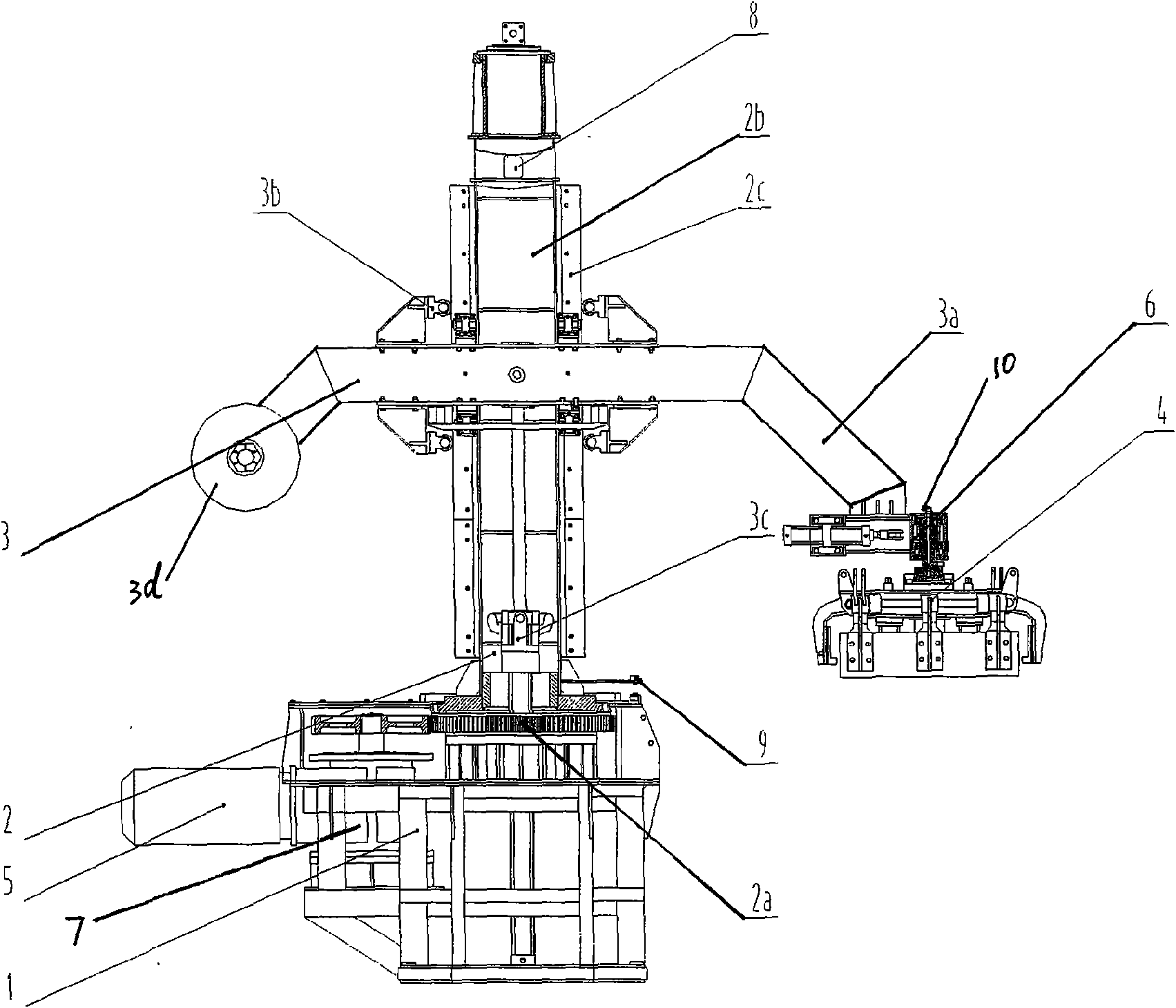
[0015] like figure 2 As shown, the present invention includes a base 1, a slewing guide rail assembly 2 mounted on the base, a lifting arm assembly 3 installed on the slewing guide rail assembly 2, and a clamp assembly 4 installed on the front end of the lifting cantilever 3a through a rotating member 6 to drive the slewing guide rail Drive mechanism 5 of assembly 2. The drive mechanism 5 is an asynchronous servo motor. The slewing guide rail assembly 2 includes a guide rail frame 2b rotatable along the slewing center 2a, and a guide rail 2c installed along the longitudinal direction of the guide rail frame. The lifting arm assembly 3 includes a lifting cantilever 3a laterally installed on the guide rail frame 2b, a roller group 3b installed on the lifting cantilever beam, and a driving cylinder member 3c connected with the lifting cantilever beam. The driving cylinder member 3c is controlled by a hydraulic proportional valve. High speed cylinder. In order to maintain the ...


PUM


Abstract

The invention provides a jib type stacking device, comprising a base (1), a revolving guide rail module (2) on the base, a lifting arm module (3) on the revolving guide rail module, a fixture module (4) on the lifting arm module, and a driving mechanism (5) for driving the revolving guide rail module, wherein, the revolving guide rail module includes a guide rail frame (2b) revolving along a revolving centre (2a), and a guide rail (2c) longitudinally arranged along the guide rail frame; the bottom end of the revolving centre (2a) is connected with the driving mechanism through a driving box (6); the lifting arm module includes a lifting cantilever (3a) transversely disposed on the guide rail frame (2b), a roller set (3b) installed on a cross beam of the lifting cantilever, and a driving cylinder component (3c) connected with the cross beam of the lifting cantilever; and the roller set (3b) is assembled and supported on the guide rail (2c). The invention has the advantages of stable structure, high stacking efficiency and flexibility.

Description

technical field [0001] The invention belongs to the technical field of object stacking device structure. Background technique [0002] In actual production, it is often necessary to stack objects layer by layer, especially for objects with different shape lengths and widths, in order to make the stacking stable and safe, two adjacent layers should be staggered and stacked at 90°. [0003] The existing stacking device is such as figure 1 The gantry structure shown is a linear movement method to realize the transfer of the material taking and stacking positions of the fixture during operation. The fixture A is installed on the longitudinal guide rail B of the mobile trolley C. When working, the trolley drive mechanism E drives the trolley C to move horizontally along the overhead transverse guide rail D to the reclaiming position, and then the clamp drive mechanism F drives the clamp A to descend to the working position along the longitudinal guide rail B of the trolley to pi...

Claims


Application Information

Patent Timeline
IPC IPC(8): B65G61/00
Inventor 张湧涛岳兴唐炜谭竹飞祝建荣
Owner KUNMING LISHEN HEAVY IND
Why Eureka
Try Eureka