
Yarn splicing guide device of automatic bobbin winder

A technology of automatic winding machine and guiding device, which is applied in the direction of transportation and packaging, conveying filamentous materials, thin material processing, etc., and can solve the problem of lower knot quality, restriction of automatic winding machine potential, and yarn guiding function Instability and other issues

Inactive Publication Date: 2009-11-18
马佐里(东台)纺机有限公司
View PDF1 Cites 6 Cited by
  • Summary
  • Abstract
  • Description
  • Claims
  • Application Information

AI Technical Summary

Problems solved by technology

This mechanism solves the coordination problem between the small suction nozzle and the yarn catcher, and greatly simplifies the transmission mechanism. When the position is above the splicer, there is a large space distance between it and the splicer and the upper yarn guide plate of the splicer, and at the same time, the guiding force point of the yarn catcher for the upper yarn is not in the splicing channel area of ​​the splicer , the joint effect of the above two makes the yarn catching hook to introduce the upper yarn into the splicing channel, and it is necessary to "over-guid" the yarn for a long distance, and the yarn catching hook must slide a long distance on the yarn Only then can the upper yarn be brought to the splicing channel of the splicer, resulting in a long guiding stroke, and the sliding of the yarn catcher and the yarn can easily aggravate yarn hairiness and even cause yarn breakage
The increase of yarn hairiness means the reduction of knot quality, which restricts the full potential of automatic winder
At the same time, the increase in the distance between the small suction nozzle and its yarn catcher and the yarn guide plate on the splicer also makes its yarn guiding effect unstable, and the guided yarn tends to deviate from the splicing channel, resulting in yarn failure. repeated splicing of threads

Method used


Image

  • Yarn splicing guide device of automatic bobbin winder
  • Yarn splicing guide device of automatic bobbin winder
  • Yarn splicing guide device of automatic bobbin winder

Examples


Embodiment Construction

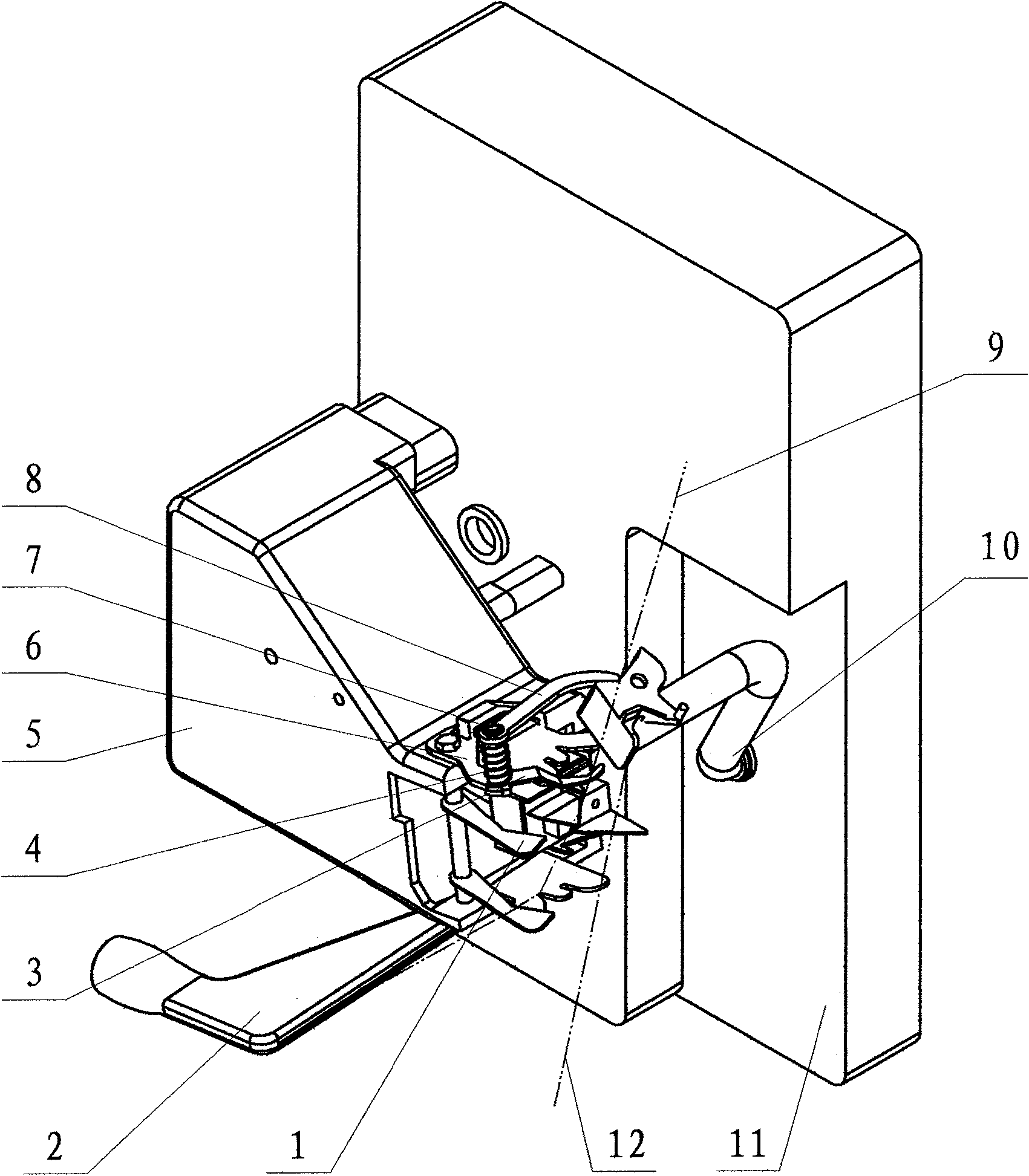
[0017] Such as figure 1 As shown, a splicer support 5 is fixedly installed on the automatic winder frame 11, and a splicer 1 is fixedly installed at the port position of the splicer support 5, and the splicer 1 adopts common air splicer. A small suction nozzle 10 is also rotatably arranged on the automatic winder frame 11, and the small suction nozzle 10 has a bent suction pipe and a suction nozzle positioned at the port of the suction pipe. Below the splicer 1, a large suction nozzle 2 that can turn upwards is arranged.

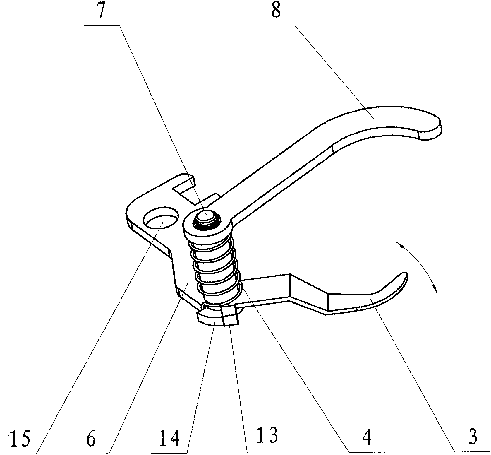
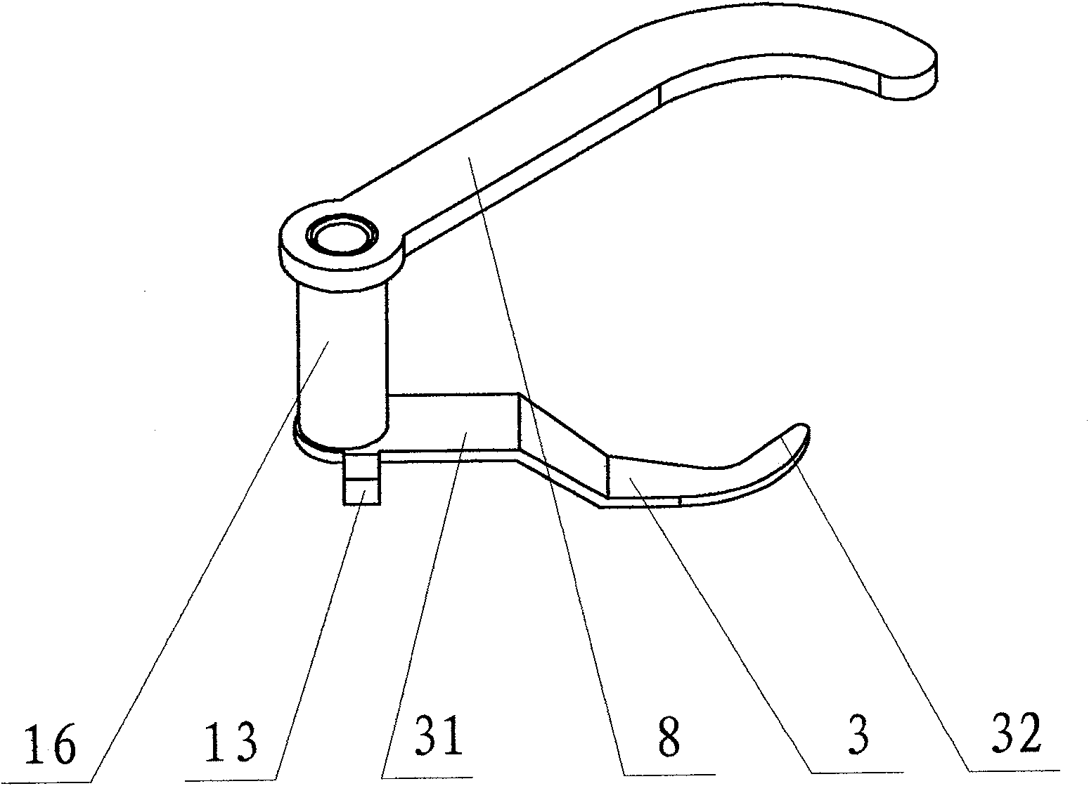
[0018] The top of the splicer 1 is provided with a yarn guide hook 3 and a guide swing arm 8 fixed to each other, the yarn guide hook 3 and the guide swing arm 8 are swingably supported on the guide bracket 6, the The guide bracket 6 is fixedly connected to the splicer support 5; therefore, the guide bracket 6 and the splicer 1 maintain a fixed positional relationship. The guide hook fulcrum 7 is vertically and fixedly arranged on the guide bracket 6 , an...


PUM


Abstract

The invention discloses a yarn splicing guide device of an automatic bobbin winder. The device comprises a splicer and a guide bracket, wherein the splicer is used for grabbing a large suction nozzle at the upper yarn end and grabbing a small suction nozzle at the lower yarn end, and the guide bracket keeps a fixed position with the splicer; the guide bracket supports a yarn guide hook in a swing mode, and the yarn guide hook is mutually and fixedly connected with a guide swing arm; the yarn guide hook and an upper yarn passage form space intersection, and an arm end part of the guide swing arm is positioned on a rotary track of the small suction nozzle; and the guide bracket is also provided with an offsetting spring for rotating and offsetting the yarn guide hook. The yarn guide hook is mutually and fixedly connected with the guide swing arm through a connecting sleeve which is sleeved on a yarn guide hook support shaft in a swing mode; the yarn guide hook support shaft is vertically and fixedly arranged on the guide bracket; and the yarn guide hook and the guide swing arm are crossed and staggered in space. The yarn splicing guide device has the advantages of simple structure, accurate yarn guide and good splicing quality, and is widely applied to various automatic bobbin winders.

Description

technical field [0001] The invention relates to a post-processing equipment of spinning machinery, especially an automatic winder used in the winding process, in particular, it guides the yarn to the splicing channel when the automatic winder performs yarn splicing s installation. Background technique [0002] The winding process is an essential process in the spinning process. After the winding process, not only can the spun bobbin be wound into bobbin yarn, so that it can be used in the subsequent process, but also the yarn impurities can be effectively removed during the winding process. And defects, improve yarn quality. Most of the traditional winding equipment use manual joints, the quality is unstable, labor intensity and manpower consumption are large; while the automatic winding machine has the advantages of high efficiency, high speed and high quality, the automatic winding machine replaces the traditional winding machine is a modern production inevitable require...

Claims


Application Information

Patent Timeline
IPC IPC(8): B65H67/08B65H69/06
Inventor 朱鹏盛晓冬张跃进张建国王平
Owner 马佐里(东台)纺机有限公司
Learn More