A 3D Focused Imaging Method for Side-Looking Tomographic Synthetic Aperture Radar

A technology of aperture radar and tomosynthesis, which is applied in the direction of utilizing re-radiation, radio wave reflection/re-radiation, measuring devices, etc., and can solve problems such as unfavorable practical applications

Inactive Publication Date: 2012-02-22
INST OF ELECTRONICS CHINESE ACAD OF SCI
View PDF3 Cites 0 Cited by
  • Summary
  • Abstract
  • Description
  • Claims
  • Application Information

AI Technical Summary

Problems solved by technology

[0012] In order to solve the problem that the existing 3D focusing imaging method and 3D ECS method are only suitable for the special observation geometry in the imaging geometry of side-looking tomosynthetic aperture radar, and the sampling interval of side-looking tomosynthetic aperture radar is too small along the elevation direction, and the The center of the synthetic aperture is located near the central plane of the imaging area of ​​the side-view tomographic synthetic aperture radar, and the ground-to-width width of the imaging area is approximately equal to the height of the imaging area, which is not conducive to practical applications. The purpose of the present invention is to provide a solution for Based on the arbitrary imaging geometry of side-view tomographic synthetic aperture radar, an accurate three-dimensional focusing imaging method that does not require geometric correction, for this reason, the present invention provides a three-dimensional focusing imaging method for side-looking tomographic synthetic aperture radar

Method used


Image

  • A 3D Focused Imaging Method for Side-Looking Tomographic Synthetic Aperture Radar
  • A 3D Focused Imaging Method for Side-Looking Tomographic Synthetic Aperture Radar
  • A 3D Focused Imaging Method for Side-Looking Tomographic Synthetic Aperture Radar

Examples


Embodiment Construction

[0070] Various details involved in the technical solution of the present invention will be described in detail below in conjunction with the accompanying drawings. It should be pointed out that the described embodiments are only intended to facilitate the understanding of the present invention, rather than limiting it in any way.

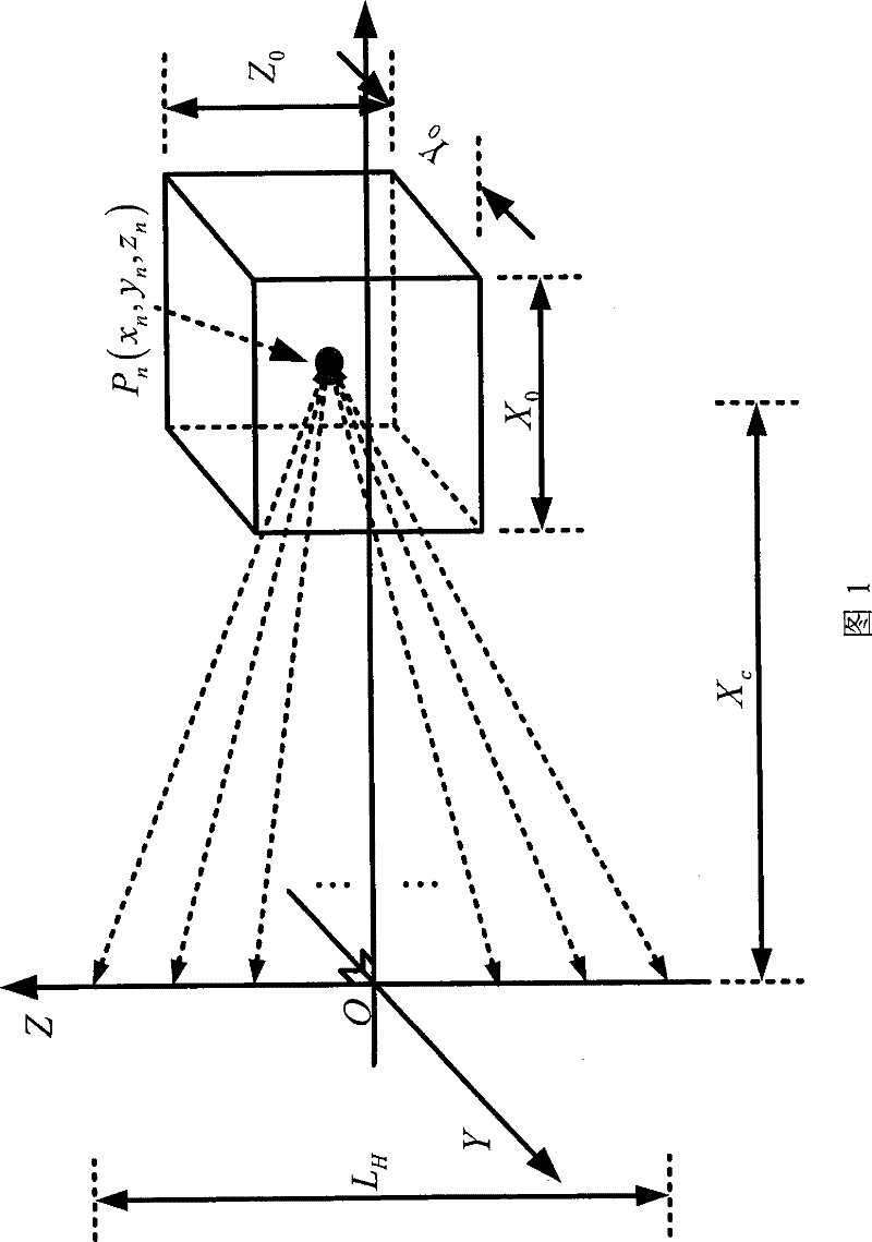
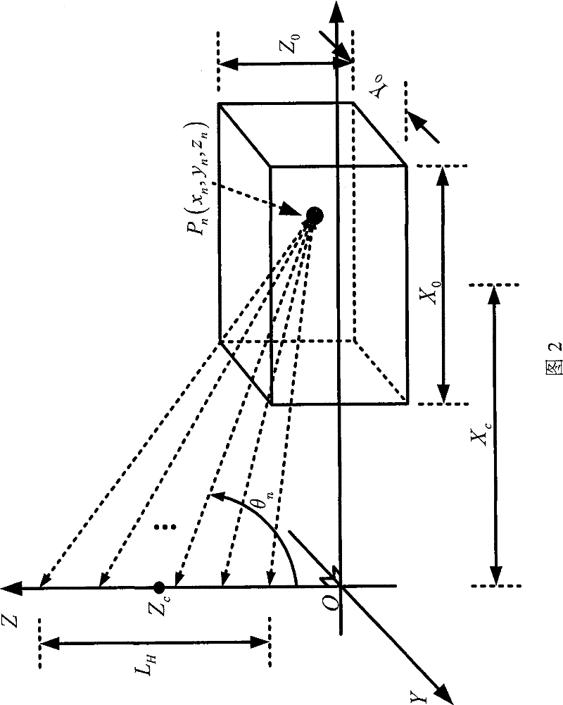
[0071] like figure 2 , OXYZ is the three-dimensional Cartesian coordinate system where the side-looking tomosynthetic aperture radar and its imaging area are located. n (x n ,y n ,z n ) is the nth point target and its coordinates in the imaging area, X 0 , Y 0 and Z 0 are the ground-range width, azimuth length, and elevation height of the imaging area, X c is the distance from the center of the imaging area to the center, Z c is the distance from the elevation of the side-looking tomosynthetic aperture radar to the center of the synthetic aperture and the plane OXY, θ n is the incident angle corresponding to the nth flight of the side-look...


PUM


Abstract

The invention is a three-dimensional focusing imaging method for side-looking tomographic synthetic aperture radar, which transforms the collected original echo data of side-looking tomographic synthetic aperture radar into the oblique range wavenumber domain and the azimuth wavenumber domain, and transforms the After the signal is recovered without aliasing in the elevation direction, the signal is transformed into the three-dimensional wavenumber domain in the oblique range direction, azimuth direction and elevation direction; the signal in the three-dimensional wavenumber domain is transformed into the Cartesian coordinate system through coordinate mapping; through Fourier inverse Transformation and image space selection are used to reconstruct the three-dimensional microwave image including the distance, azimuth and elevation spatial position information of the imaging area as well as the amplitude and phase information. This method can accurately reconstruct the 3D microwave image of the imaging area without geometric correction when the number of samples in the elevation direction is small, the distribution of the synthetic aperture center in the elevation direction is arbitrary, or the size of the imaging area is arbitrary. This method can also be used for three-dimensional microwave image reconstruction in imaging observation geometries such as down-view and side-view tomography SAR.

Description

technical field [0001] The invention relates to the technical field of information acquisition and processing, in particular to a three-dimensional focusing imaging method for side-view tomography synthetic aperture radar, which can acquire three-dimensional microwave images of imaging regions. Background technique [0002] Side-looking tomosynthetic aperture radar is a new three-dimensional synthetic aperture radar imaging technology, such as figure 1 , where OXYZ is the three-dimensional Cartesian coordinate system where the side-looking tomosynthetic aperture radar and its imaging area are located, and P n (x n ,y n ,z n ) is the nth point target and its coordinates in the imaging area, X 0 , Y 0 and Z 0 are the ground-range width, azimuth length, and elevation height of the imaging area, X c is the distance from the center of the imaging area. By conducting multi-view observations on the same imaging area along the elevation direction at different heights Z, a se...

Claims


Application Information

Patent Timeline
Patent Type & Authority Patents(China)
IPC IPC(8): G01S7/02G01S13/90
Inventor 洪文谭维贤王彦平吴一戎
Owner INST OF ELECTRONICS CHINESE ACAD OF SCI
Why Eureka
Try Eureka