Pneumatic tire

A technology for pneumatic tires and tires, which is applied in the direction of pneumatic tires, special tires, tire parts, etc. It can solve the problems of poor adhesion, difficulty in suppressing air leakage, and failure to solve the adhesion between the air-proof layer and the surrounding rubber layer. Excellent adhesion without deteriorating durability

Inactive Publication Date: 2009-11-18
THE YOKOHAMA RUBBER CO LTD
View PDF4 Cites 5 Cited by
  • Summary
  • Abstract
  • Description
  • Claims
  • Application Information

AI Technical Summary

Problems solved by technology

However, in this case, since the diene-based rubber generally used in the sidewall portion has poor adhesion to butyl rubber, from the viewpoint of durability, a butyl rubber rubber is arranged on the sidewall portion with large bending deformation. There is a very big problem in the anti-breathing layer formed by the rubber composition with rubber as the main body
[0004] In addition, there have been proposed structures in which a material with a low air permeability coefficient is arranged between a reinforcing member such as a chafer in the bead portion and a carcass layer (for example, refer to Cited Document 3), and an inner liner layer is arranged so as to be wound into the carcass layer. to the underside of the bead core (for example, refer to Patent Document 4), but these structures, as described above, are difficult to suppress the leakage of air from the rolled-up portion of the carcass layer to the outer surface of the tire, and do not solve the problem caused by the use of butyl Adhesion between the air-permeable barrier layer and the surrounding rubber layer formed by the rubber composition mainly composed of rubber

Method used


Image

  • Pneumatic tire
  • Pneumatic tire
  • Pneumatic tire

Examples


Embodiment

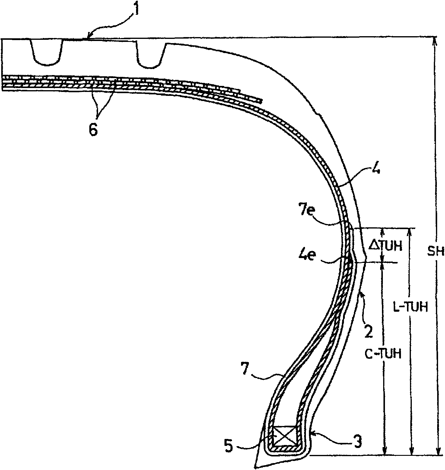
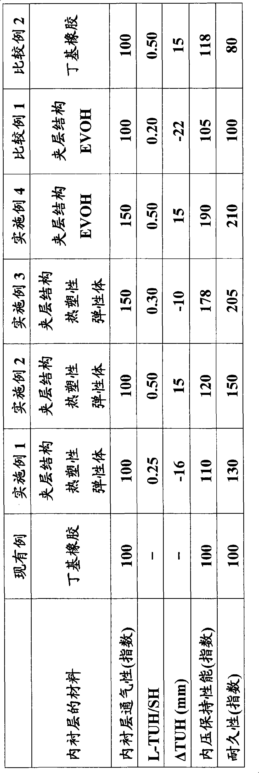
[0045] Tires of Conventional Example, Examples 1-4, and Comparative Examples 1-2 were produced. The tire size is 195 / 60R15. In these tires, a carcass layer containing a plurality of reinforcing cords is spanned between a pair of bead portions, and the carcass layer is wound around the bead core from the inner side to the outer side of the tire. The constituent material of the inner liner on the inner cavity side, the ratio of the turn-up height (L-TUH) of the inner liner to the tire section height (SH) (L-TUH / SH), and the turn-up height of the carcass layer ( The difference (ΔTUH) between C-TUH) and the rolled-up height (L-TUH) of the inner liner is different.

[0046] The tire of the conventional example employs an inner liner layer having a thickness of 0.5 mm formed of a rubber composition mainly composed of butyl rubber, and the inner liner layer is terminated on the inner surface of the tire. The tires of Examples 1 to 3 employ an inner liner with a thickness of 0.5 mm ...


PUM


Abstract

Provided is a pneumatic tire: in which a film made of a thermoplastic resin or a thermoplastic elastomer composition obtained by blending an elastomer in a thermoplastic resin is used for an inner liner layer; and which is improved in its internal pressure holding performance while maintaining its durability satisfactorily. The pneumatic tire according to the present invention is a pneumatic tire in which: a carcass layer including multiple reinforcing cords is laid between paired bead parts; and the carcass layer is wound up around each of bead cores from the inner side to the outer side of the tire. In the pneumatic tire, an inner liner layer including a film made of the thermoplastic resin or the thermoplastic elastomer composition obtained by blending the elastomer in the thermoplastic resin is disposed on a tire inner cavity side of the carcass layer, the inner liner layer is wound up around each bead core from the inner side to the outer side of the tire, and the winding-up height (L-TUH) of the inner liner layer is set at 25% or more of the sectional height (SH) of the tire.

Description

technical field [0001] The present invention relates to a pneumatic tire whose inner liner uses a film formed of a thermoplastic resin or a thermoplastic elastomer composition in which an elastomer is mixed with a thermoplastic resin. More specifically, it relates to a pneumatic tire capable of increasing internal pressure while maintaining sufficient durability. Air-filled tires that maintain performance. Background technique [0002] Conventionally, in pneumatic radial tires having at least one carcass layer, in order to suppress air leakage, the innerliner disposed on the innermost surface of the tire has been thickened, or a material having a low air permeability coefficient has been used for the innerliner. However, when the inner liner is thickened, the weight of the tire increases and the rolling resistance deteriorates accordingly. On the other hand, when a material with a low air permeability coefficient is used for the inner liner (for example, refer to Patent Doc...

Claims


Application Information

Patent Timeline
Patent Type & Authority Applications(China)
IPC IPC(8): B60C5/14
CPCB60C1/0008B29D2030/0682B60C15/0036B60C5/14B60C2005/145B60C2015/009Y10T152/10855
Inventor 松田淳原祐一
Owner THE YOKOHAMA RUBBER CO LTD
Why Eureka
Try Eureka