Handle for pipes

A technology for handles and catheters, applied in catheters, applications, medical science, etc., can solve the problems of time-dependent changes in fastening strength, decrease in the fastening force of ring-shaped elastic parts, and difficult operation, and achieve the effect of less time-dependent changes

Inactive Publication Date: 2009-11-25
JAPAN LIFELINE CO LTD
View PDF1 Cites 1 Cited by
  • Summary
  • Abstract
  • Description
  • Claims
  • Application Information

AI Technical Summary

Problems solved by technology

[0006] However, in the existing handle, in order to improve the braking performance, if the fastening force of the annular elastic member is to be enhanced, the movement operation of the operating part of the handle becomes heavy from the beginning, and the operation is difficult.
In addition, if the operability is to be improved, the fastening force of the ring-shaped elastic member is reduced, and the braking performance is reduced, and it is difficult to finely adjust the fastening st

Method used


Image

  • Handle for pipes
  • Handle for pipes
  • Handle for pipes

Examples


Embodiment Construction

[0034] Hereinafter, the present invention will be described based on the embodiments shown in the drawings.

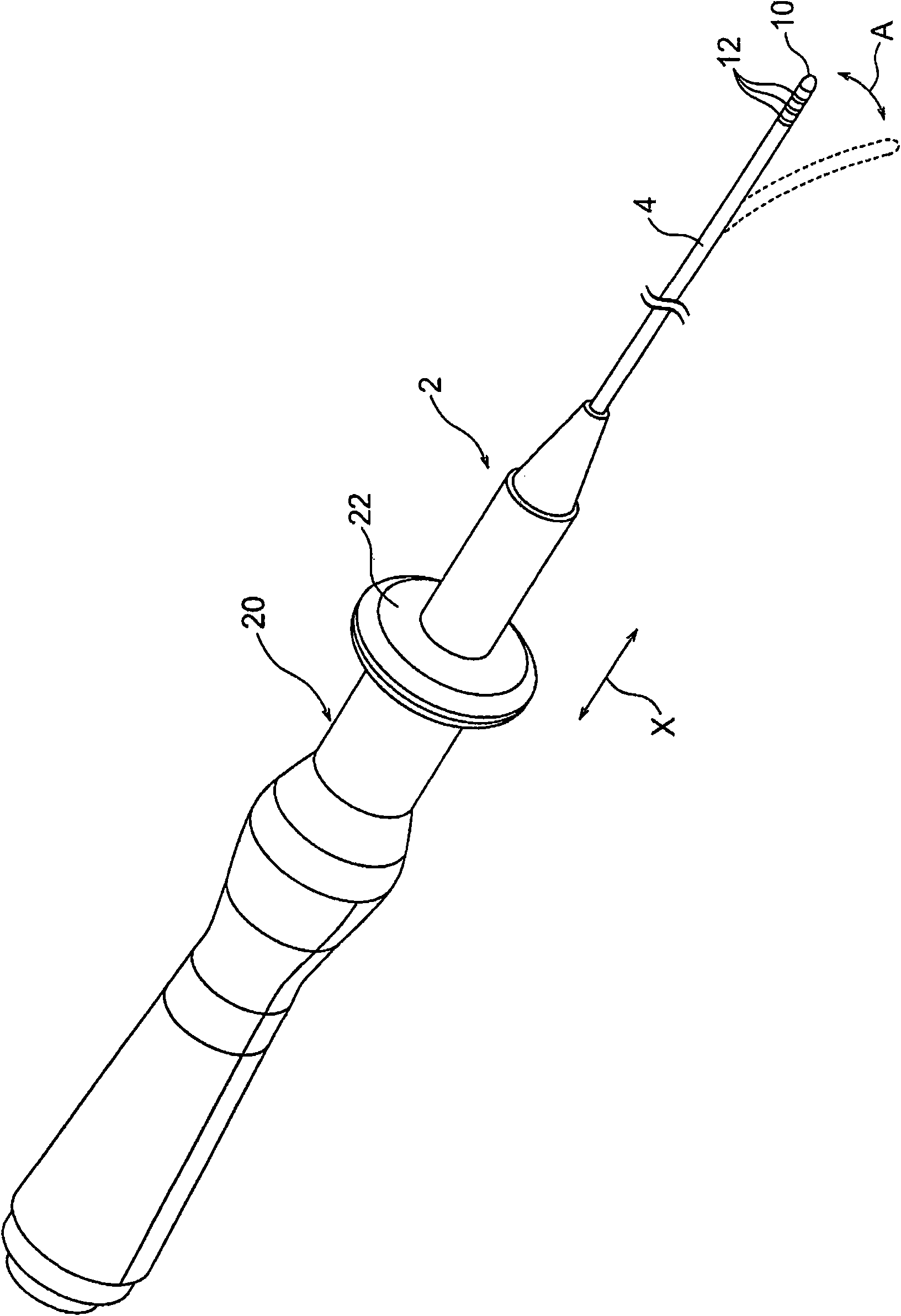
[0035] Such as figure 1 As shown, the front end involved in an embodiment of the present invention can be biased towards the operation catheter 2, such as for the diagnosis or treatment of arrhythmia, and the distal end of the catheter tube (tube part) 4 is equipped with a front end piece 10 and multiple 12 middle rings. The front end piece 10 and the intermediate ring 12 function as electrodes, and are connected and fixed to the catheter tube 4 by, for example, bonding with an adhesive.

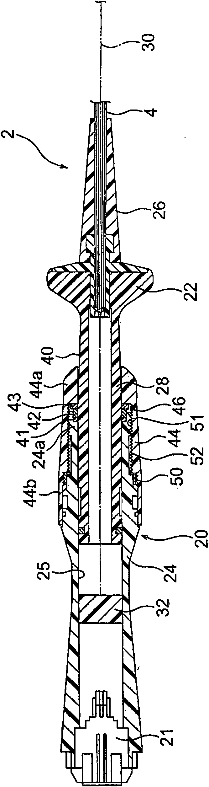
[0036] A handle body 20 is installed at the proximal end of the catheter tube 4 . Wires are pulled through the inside of the catheter tube 4 and the handle body 20 , and the front ends of the wires are electrically connected to the front end piece 10 and the intermediate ring 12 that constitute electrodes. In addition, the base ends of these wires are fixed to the figure 2 A con...


PUM


Abstract

The invention provides a handle for pipes, wherein an operation part can be easily stopped at any radial position, the operation force of the operation part can be in fine adjustment, and the ageing of fastening force is little changed once the fastening force is set. The handle for pipes has: a handle body (24); an button for operation (22) having a medial axle part (28) moved along the axial direction and freely installed in the axle hole of the handle body (24); a front end cover (44) positioned at the periphery of the medial axle part (28), freely moved along the axial direction, and rotationally bolt-jointed with the far end of the handle body (24) surrounding the axle core; an annular elastic component (42) between the far end of the handle body (24) and the far end of the front end cover (44) and positioned at the inner periphery of the front end cover (44) and the outer periphery of the medial axle part (28), in which the fastening force at the outer periphery of the medial axle part (28) is changed according to the axial bolt-jointed position relative to the front end cover (44) of the handle body (24); and ratchet feel endowing mechanisms (50, 54) installed between the front end cover (44) and the handle body (24) and endowing the ratchet feel according to the rotational pitch angle (theta).

Description

technical field [0001] The present invention relates to a catheter handle, and more particularly relates to a catheter handle capable of finely adjusting the operating force of an operation unit. Background technique [0002] Various catheters have been proposed as medical catheters. A handle for the catheter is usually provided on the proximal end side of the catheter. Various catheter handles have been proposed depending on the type of catheter. [0003] For example, the operation portion of the catheter handle may be manipulated, and the distal end portion of the catheter may be bent or stretched when the catheter is intended to be bent. [0004] As a catheter handle used in this case, for example, as shown in Patent Document 1 below, a handle having a piston structure in which a driving member is incorporated in a long tube has been proposed. In this conventional handle, by moving the piston in the axial direction relative to the cylinder, the distal end portion of th...

Claims


Application Information

Patent Timeline
IPC IPC(8): A61M39/00A61B5/00A61B18/14A61M25/01
CPCA61M25/0136
Inventor 大川靖洋
Owner JAPAN LIFELINE CO LTD
Why Eureka
Try Eureka