

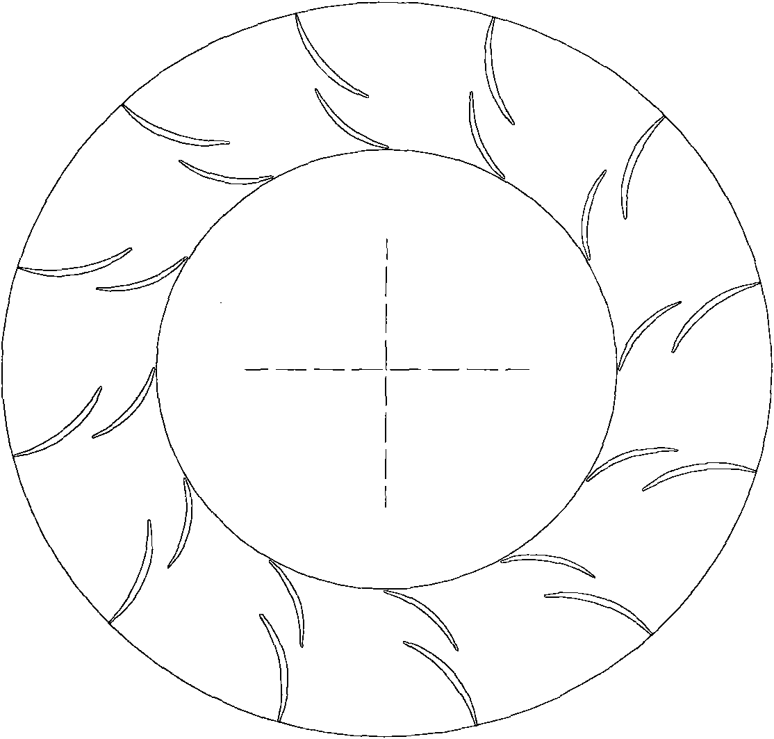
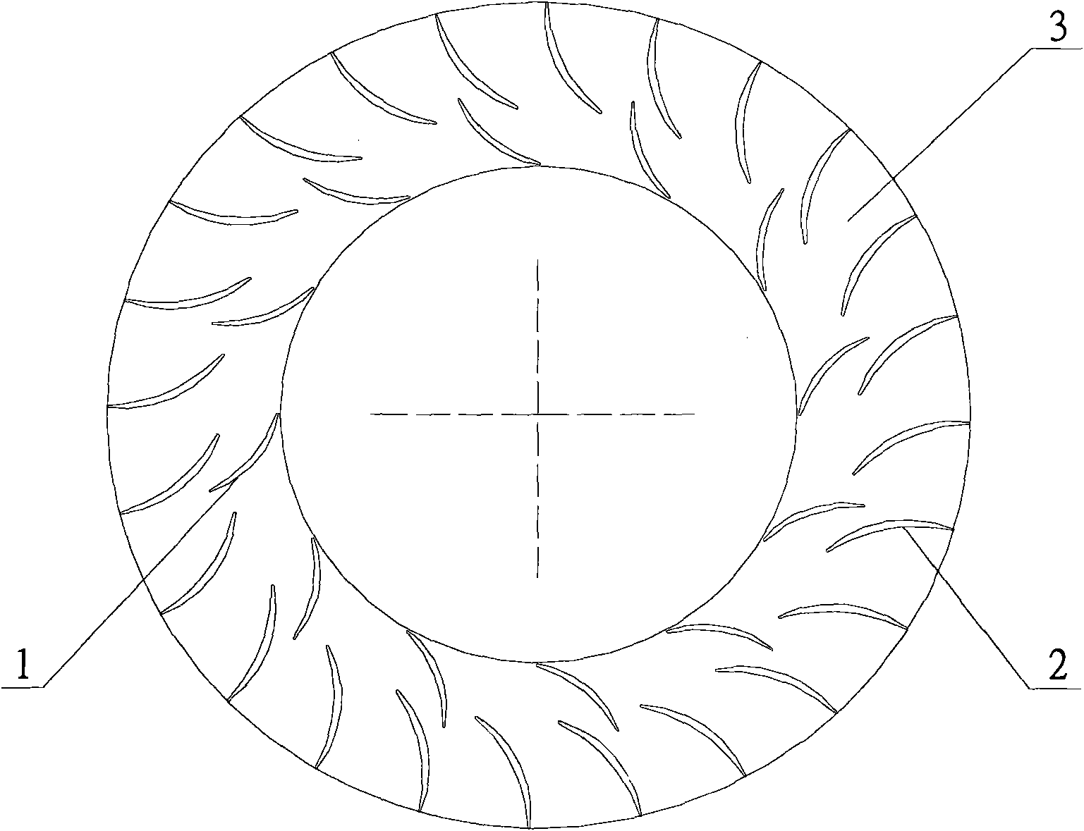
1/2-type tandem-blade diffuser
A diffuser and vane type technology, which is applied in the field of tandem vane diffusers, can solve the problems of narrow stable operation range and small pressurizing capacity of the rear vanes, so as to expand the effective flow area and improve the diffusing capacity. , the effect of reducing surge flow
- Summary
- Abstract
- Description
- Claims
- Application Information
AI Technical Summary
Problems solved by technology
Method used
Image

Examples
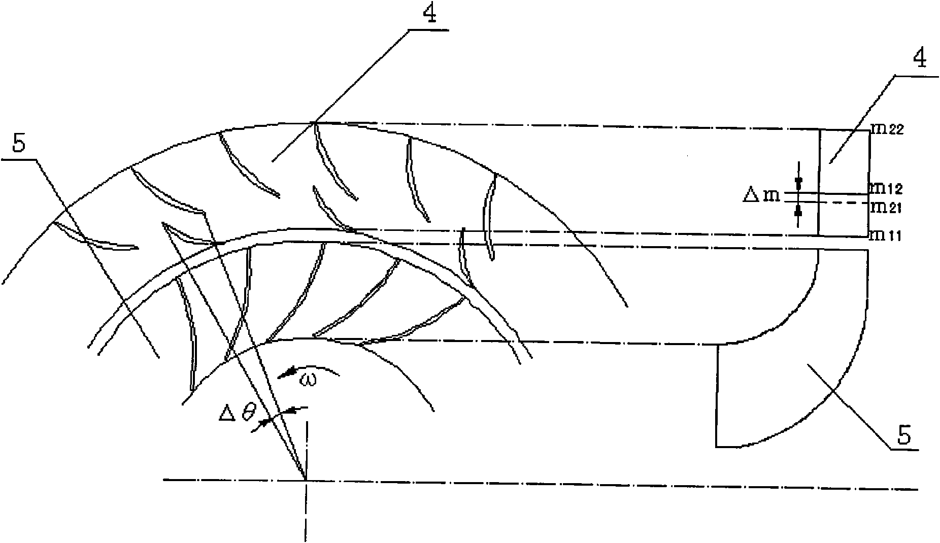
Embodiment 1
[0025] Embodiment 1, when the overlapping degree Δm of the rear row of blades 2 and the front row of blades 1 = 20%, the staggered degree Δθ of the rear row of blades and the front row of blades is 5%, and the relative division position m of the rear row of blades and the front row of blades is 20%;
Embodiment 2
[0026] Embodiment two, when the inlet of the rear row of blades 2 is flush with the outlet of the front row of blades 1, that is, when Δm=0%, the staggered degree Δθ of the rear row of blades and the front row of blades is 25%, and the rear row of blades and the front row of blades The relative split position m is 40%;
Embodiment 3
[0027] Embodiment 3, when the overlapping degree Δm=-5% of the rear row of blades 2 and the front row of blades 1, the staggered degree Δθ of the rear row of blades and the front row of blades is 45%, and the relative division positions of the rear row of blades and the front row of blades m is 70%.
PUM
 Abstract
Description
Claims
Application Information