High-radiating light-emitting diode module and light-emitting diode lamps
A technology of light-emitting diodes and high heat dissipation, which is applied to semiconductor devices of light-emitting elements, light sources, point light sources, etc., and can solve the problems of reduced lighting brightness, large volume, and difficulty in increasing the number of radiators
- Summary
- Abstract
- Description
- Claims
- Application Information
AI Technical Summary
Problems solved by technology
Method used
Image

Examples
Embodiment Construction
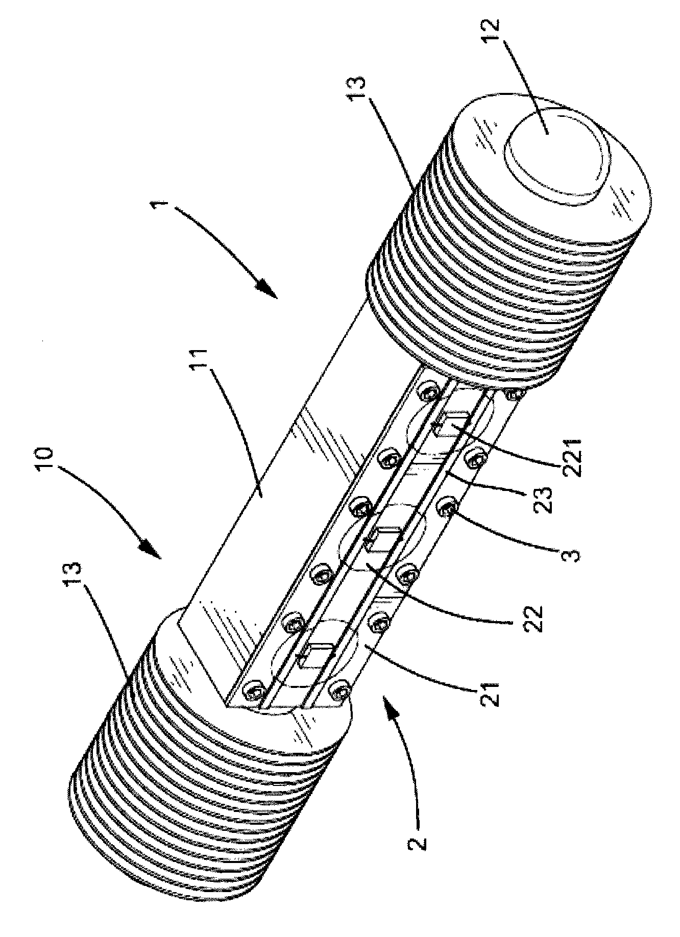
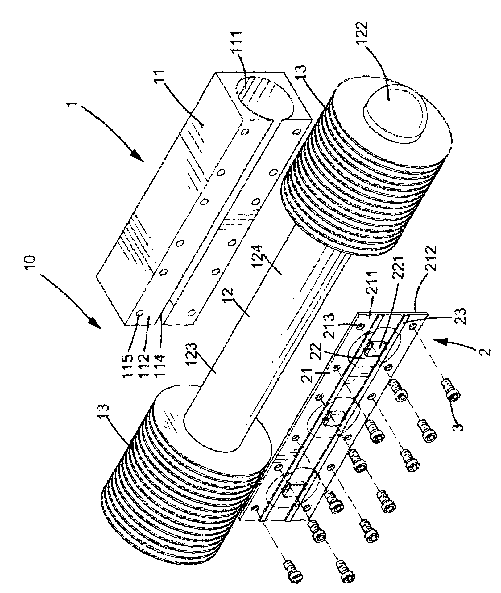
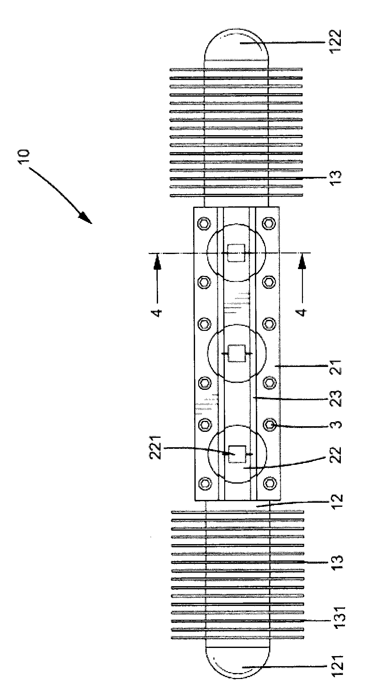
[0065] see Figure 1 to Figure 4 , shows the LED module 10 according to the first embodiment of the present invention; the LED module 10 includes an LED light source assembly 2 and a heat dissipation module 1 .
[0066] The light emitting diode light source assembly 2 includes a substrate 21 made of metal material and a plurality of light emitting diodes 22; the metal substrate has a first surface 211 and a second surface 212 opposite to each other, and a circuit board 23 is combined on the first surface 211 Each light emitting diode 22 is combined on the first surface 211 of the substrate and includes at least one light emitting diode chip 221 electrically connected to the circuit board 23 . In this embodiment, the substrate 21 is provided with a plurality of through holes 213, and the thickness of the substrate 21 is 0.5-1 mm.
[0067] The heat dissipation module 1 includes a heat dissipation body 11, a heat pipe 12 and two fin radiators 13; the interior of the heat dissipa...
PUM
 Abstract
Description
Claims
Application Information
PatSnap Eureka turns technology decisions into work you can execute. Powered by our Innovation Knowledge Graph, it runs expert workflows across engineering, life sciences, materials and intellectual property. Get your review-ready output in minutes.


