Rapid hot water generator

A generator, hot water technology, applied in water heaters, fluid heaters, lighting and heating equipment, etc., can solve the problems of low energy utilization, low heat exchange efficiency, etc., achieve light weight, high safety, structure simple effect

Inactive Publication Date: 2009-11-25
克雷登热能设备(浙江)有限公司
View PDF1 Cites 4 Cited by
  • Summary
  • Abstract
  • Description
  • Claims
  • Application Information

AI Technical Summary

Problems solved by technology

[0002] At present, the demand for hot water for civil and industrial use is increasing. Most of the existing technologies use straight pipes and serpentine pipe groups as the heat transfer surface. The heat exchange efficiency is low and the energy utilization rate is low.

Method used


Image

  • Rapid hot water generator
  • Rapid hot water generator
  • Rapid hot water generator

Examples


Embodiment Construction

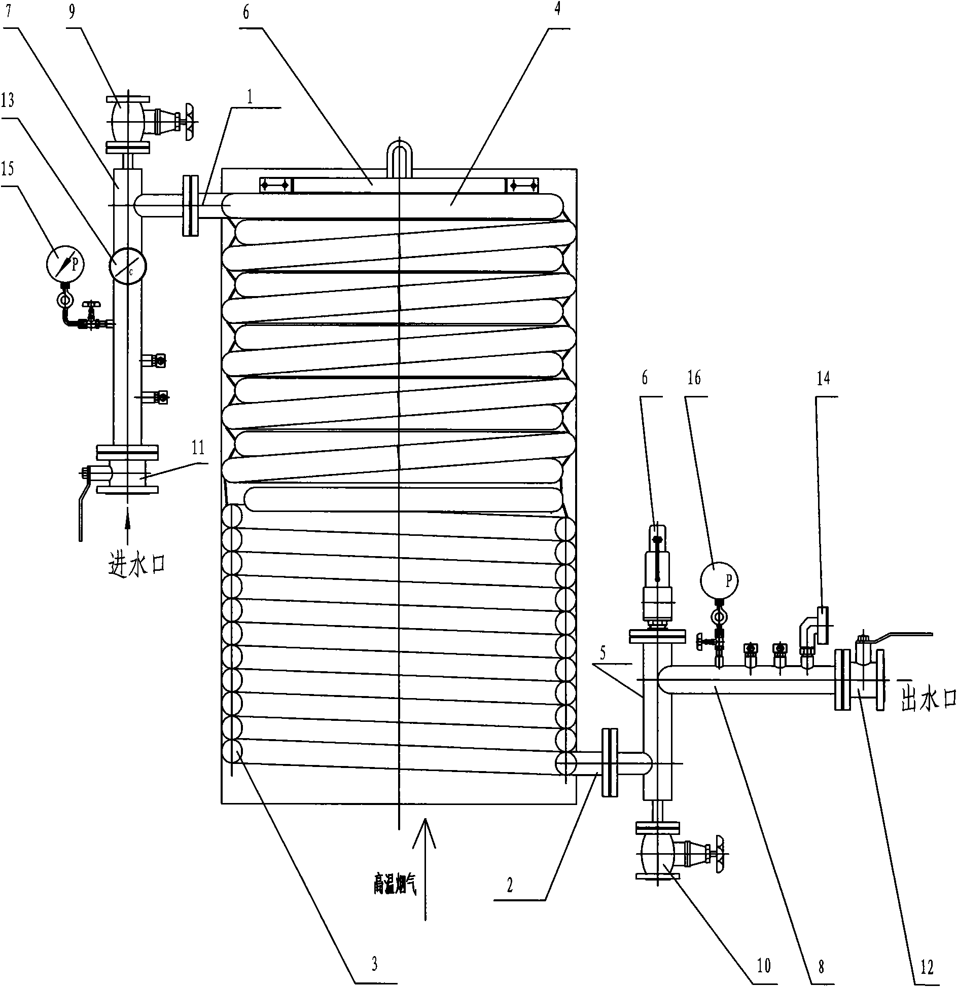
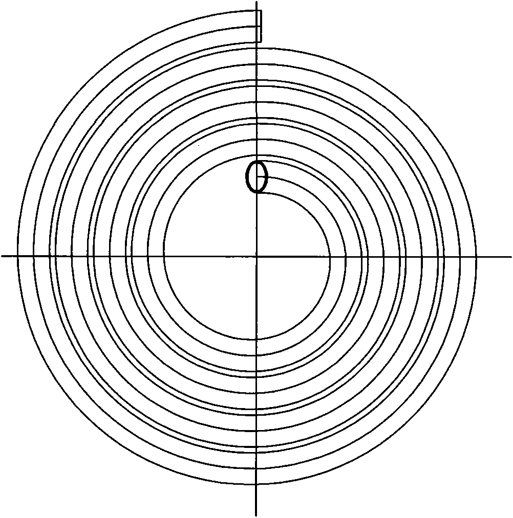
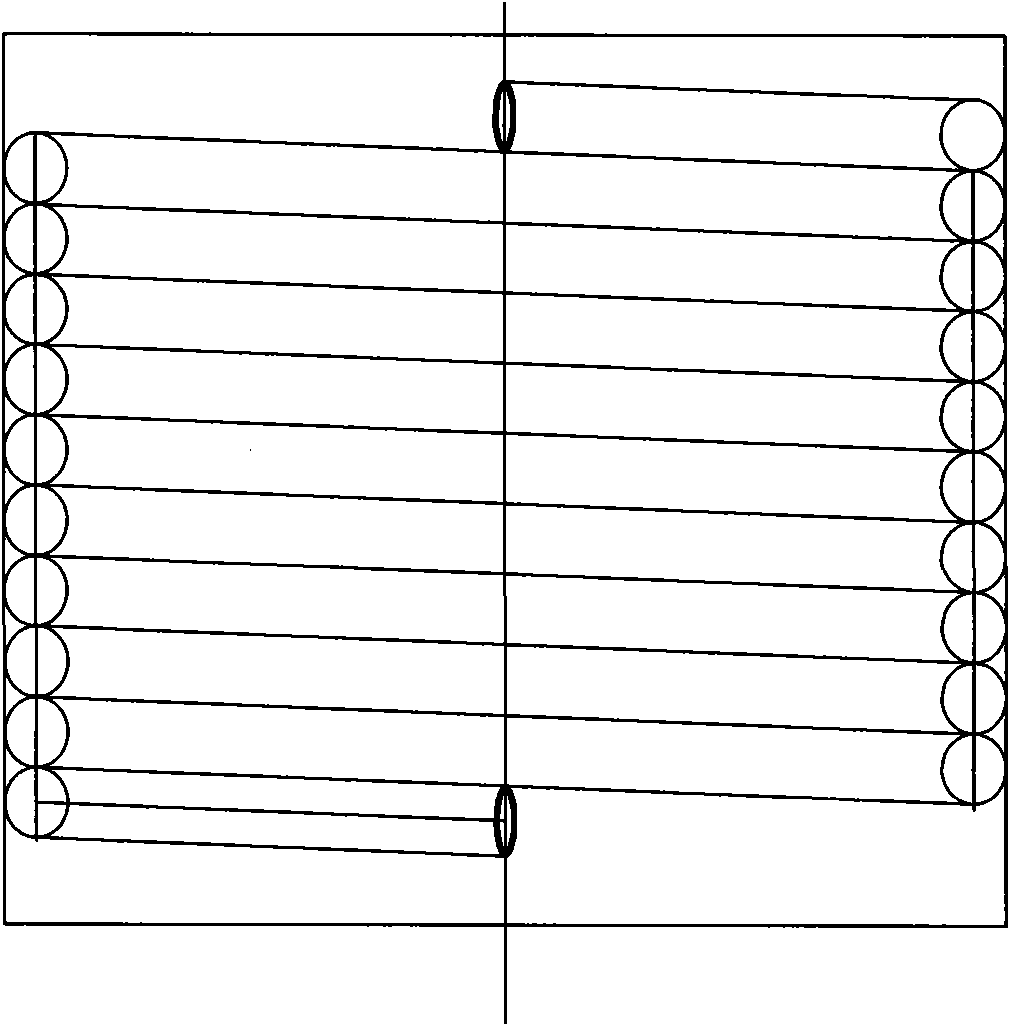
[0016] refer to figure 1 , figure 2 , image 3 , a rapid hot water generator, including a heat exchanger and a heating device, the heat exchanger adopts a coil device connected in series, and the upper part of the coil device is formed by a multi-layer mosquito-repellent-repellent flat coil 4 to form a convection On the heating surface, the lower part of the coil device is closely opposed by the helical spring-shaped coil 3 to form a cylindrical combustion chamber. The top of the coil device is provided with a cold water inlet 1, and the bottom of the coil device is provided with a hot water outlet 2.

[0017] The heating device adopts a high-temperature flue gas heat source, and the high-temperature flue gas heat source is located below the coil device.

[0018] The cold water inlet 1 is connected to the water inlet main pipe 7, and the water inlet main pipe 7 end is provided with a water inlet valve 11; the hot water outlet 2 is connected to the water outlet main pipe 8, ...


PUM


Abstract

The invention relates to a rapid hot water generator comprising a heat exchanger and a heating apparatus. The heat exchanger uses a coil installation connected in series by coils. Multilayer mosquito incense shape flat coil at the upper side of the coil installation forms a convection heating surface. A spiral spring coil at the lower side leaning against forms a cylindrical combustion chamber. The coil installation is provided with a cool water inlet at the top and a hot water outlet at the bottom. Compared with prior art, the hot water generator of the invention occupies small area in light weight and less steel consumption. It is simple in structure and easy to operate and maintain; outlet temperature and pressure are stable and reliable. Output temperature and water amount can be rapidly regulated with changed load. The invention has multiple temperature and pressure protection and extremely high security.

Description

(1) Technical field [0001] The invention relates to a quick hot water generator. (2) Background technology [0002] At present, the demand for hot water for civil and industrial use is increasing. Most of the existing technologies use straight tubes and serpentine tube groups as heat transfer surfaces, which have low heat exchange efficiency and low energy utilization. [0003] Chinese invention patent CN2682334 discloses a serpentine tube heating furnace, which effectively solves the problems of slow heating and energy waste. Its technical solution is to install a rain cover on the chimney mouth on the upper part of the furnace body through a support body, and install the furnace through a support block inside the furnace body. There is a slag door at the lower part of the support block of the furnace bar, and there is a fuel door on the furnace body above the furnace bar. There are upper and lower dust-cleaning doors on the upper and lower furnace body of the shaped heati...

Claims


Application Information

Patent Timeline
Patent Type & Authority Applications(China)
IPC IPC(8): F24H1/16F24H9/16F24H9/20
Inventor 王志强黄坚应连岗王洪勇朱锋郭昕红
Owner 克雷登热能设备(浙江)有限公司
Why Eureka
Try Eureka