Needle track inspection device, detecting device and needle track checking procedure

A technology of an inspection device and an inspection method, applied in the directions of measuring devices, measuring electricity, measuring electrical variables, etc., can solve the problems of discriminating the electrode pad 100, not recording the content of the discrimination of chips, unqualified chips, etc., and achieving the effect of reducing the burden.

Active Publication Date: 2009-11-25
TOKYO ELECTRON LTD
View PDF5 Cites 9 Cited by
  • Summary
  • Abstract
  • Description
  • Claims
  • Application Information

AI Technical Summary

Problems solved by technology

Therefore, in the case of determining the exposed area 111 using existing devices, as Figure 18 shown, from Figure 18 The black and white image of (a) is obtained Figure 18 In the binarized image shown in (b), it is impossible to distinguish between the shadow part 112 and the exposed area 111 of the chips
Therefore, there will be a problem that the exposed area 111 is misrecognized as the shadow portion 112 of the chip, and the chip on which the exposed area 111 is formed is determined to be a good product; or conversely, the shadow portion 112 of the chip is misidentified as the ex

Method used


Image

  • Needle track inspection device, detecting device and needle track checking procedure
  • Needle track inspection device, detecting device and needle track checking procedure
  • Needle track inspection device, detecting device and needle track checking procedure

Examples


no. 1 approach

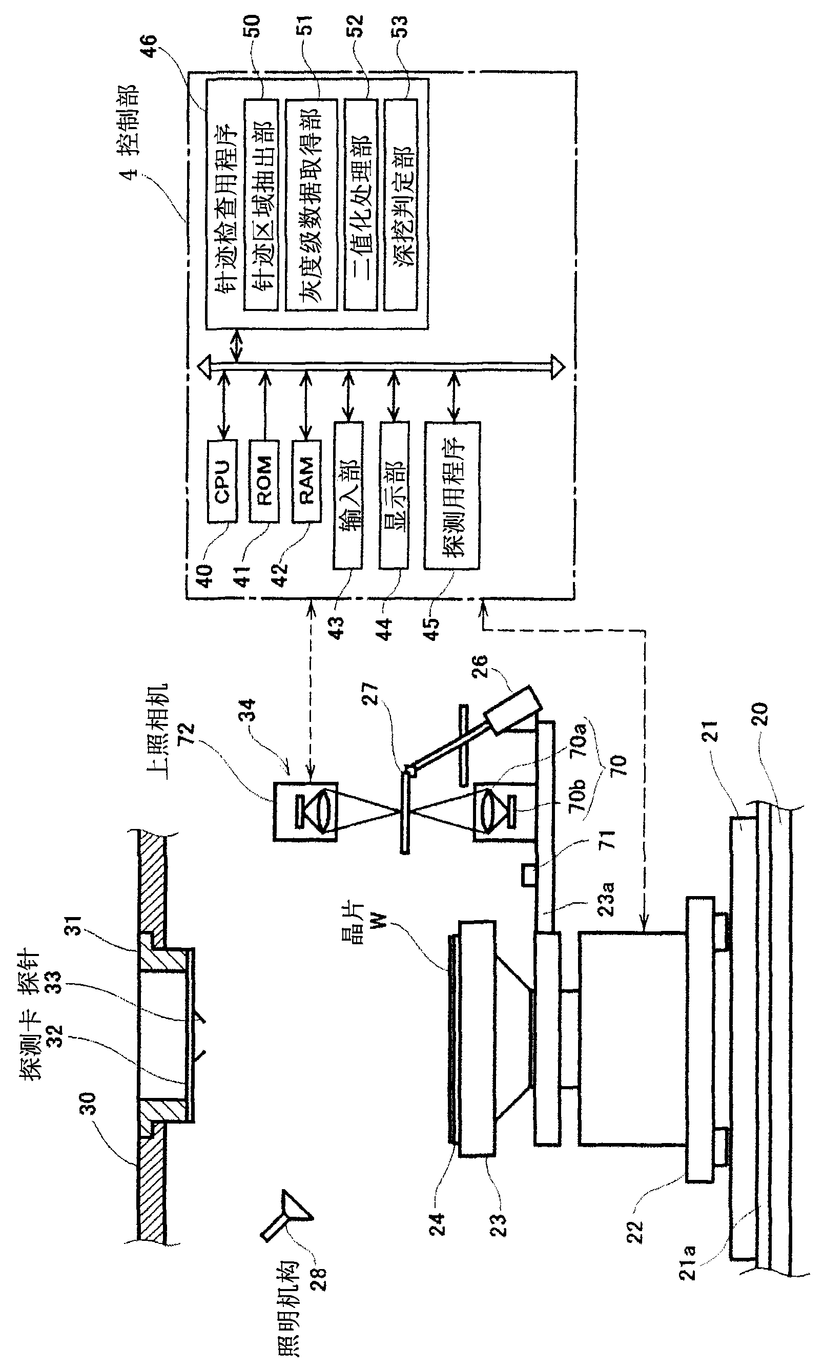
[0078] figure 1 It is a figure which shows the detection apparatus which incorporates the stitch inspection apparatus which concerns on embodiment of this invention. This detection device has a base 20 on which a first table 21 is placed in a state of being movably supported on a first guide rail 21 a extending in parallel in the X direction, and the first table 21 is penetrated by an axis. A ball screw and a motor (not shown) of the stage 21 can move in the X direction shown in the figure. In addition, on the first table 21, in the same manner as the first table 21, the second table 22 is placed so as to be movable in the unillustrated Y direction perpendicular to the X and Z directions. , on the second table 22, there is placed a third table 23 that can move in the illustrated Z direction by a motor not shown.

[0079] On the moving body of the third workbench 23, there is provided with the Z-axis as the center of rotation and only a slight amount of rotational freedom (t...

no. 2 approach

[0107] refer to Figure 11 with Figure 14 A second embodiment of the present invention will be described. Figure 11 In the detection device of the second embodiment shown, the stitch inspection program 46 is provided with a filter processing unit 54 as means for performing the filter processing of the present invention. The filter processing section 54 is in Figure 12 In the process of step S5 in the shown flowchart, the imaging data D1 is subjected to filtering processing to make the boundary between the dark portion and the bright portion of the imaging data D1 unclear, and the imaging data D1 is converted into corrected imaging data D3. Then, in the present embodiment, the pattern 14 is generated based on the corrected imaging data D3. In addition, in Figure 12 In the shown flowchart, the same processing as that of step S1 to step S4 of the first embodiment is performed in steps S1 to S4, and the same processing as that of step S5 to step S12 of the first embodiment...

Embodiment

[0112] Experiments for confirming the effects of the present invention will be described. First, as a first experiment, using the detection device of the first embodiment, the Figure 15 The four electrode pads 2 a to 2 b shown are inspected to confirm whether or not the exposed region 11 is formed on the stitch 10 . Of these four electrode pads 2a to 2b, the exposed regions 11 are formed on the electrode pads 2a and 2b, and the exposed regions 11 are not formed on the electrode pads 2c and 2d.

[0113] The result of the first experiment was to generate Figure 16 Patterns 14a-14b are shown. In the patterns 14a, 14b corresponding to the electrode pads 2a, 2b, there are two lower regions formed between regions with higher pixel values, and the average value h1 of the gray scale is about 120. Therefore, even if The binarized pattern is obtained, and this area is also an area where the pixel value is "0" and the other areas are "1". Therefore, the logic pattern matches the re...


PUM


Abstract

The invention provides a needle track inspection device, a detecting device with the same and a needle track checking procedure, capable of automatically detecting whether a basal layer of an electrode pad is exposed at the high precision. The needle track inspection device comprises a needle track region withdrawing part (50) for withdrawing the needle track region (13) from camera shooting data (D1), wherein the camera shooting data (D1) being obtained by a camera (72) for shooting an electrode pad (2), a greyscale grade data obtaining part (51) for obtaining the greyscale pattern corresponding to the pixel grey level and the pixel position on a center line (P) extending in the length direction of the needle track region for the needle track region (13), and a deep dug judging part (53) for judging whether the basal layer (6) is exposed based on the obtained greyscale pattern and the reference pattern when the basal layer (6) is exposed out of the needle track (10).

Description

technical field [0001] The present invention relates to a stitch inspection device, a stitch inspection method, and a detection device equipped with the stitch inspection device, which automatically detects exposure conditions such as the presence or absence of the base layer of electrode pads on a substrate after inspection using a probe. Background technique [0002] Conventionally, a probe device has been used as a device for measuring electrical characteristics of an IC chip formed on a semiconductor substrate. The probing device includes a table on which the substrate is placed and can move freely in the three-dimensional direction, and a probe card. The so-called probe test is performed, that is, the probes of the probe card are brought into contact with the electrode pads, which are in contact with the electrode pads on the substrate. The wiring patterns are connected to perform electrical measurements on the chip. [0003] Generally, a probe is used as a probe, and ...

Claims


Application Information

Patent Timeline
IPC IPC(8): G01N21/956G01R31/28
CPCG01R1/067G01R31/2886G01R31/311G06T7/0004
Inventor 梅原康敏月嶋慎河野功佐野聪
Owner TOKYO ELECTRON LTD
Why Eureka
Try Eureka