Post-positioning device and method based on pick-up head and application thereof

A camera, post-positioning technology, applied in the input/output process of data processing, instruments, electrical digital data processing, etc. Wide range of applications, flexible operation, and the effect of avoiding light spots

Inactive Publication Date: 2009-11-25
GUANGDONG VTRON TECH CO LTD
View PDF0 Cites 10 Cited by
  • Summary
  • Abstract
  • Description
  • Claims
  • Application Information

AI Technical Summary

Problems solved by technology

[0004] 1. The cost is high, and the requirements for each equipment are relatively high, which is not conducive to popular use;
[0005] 2. The light from the four backlight sources (2) illuminating the screen (1) has obvious strengths and weaknesses, and there may be an obvious overlapping area in the middle of the screen (1), the light will be stronger, and the reflected light will be in the The camera (3) images and shows light spots, which affects the quality of touch positioning, and it is difficult to report the position correctly when multi-touch

Method used


Image

  • Post-positioning device and method based on pick-up head and application thereof
  • Post-positioning device and method based on pick-up head and application thereof
  • Post-positioning device and method based on pick-up head and application thereof

Examples


Embodiment 1

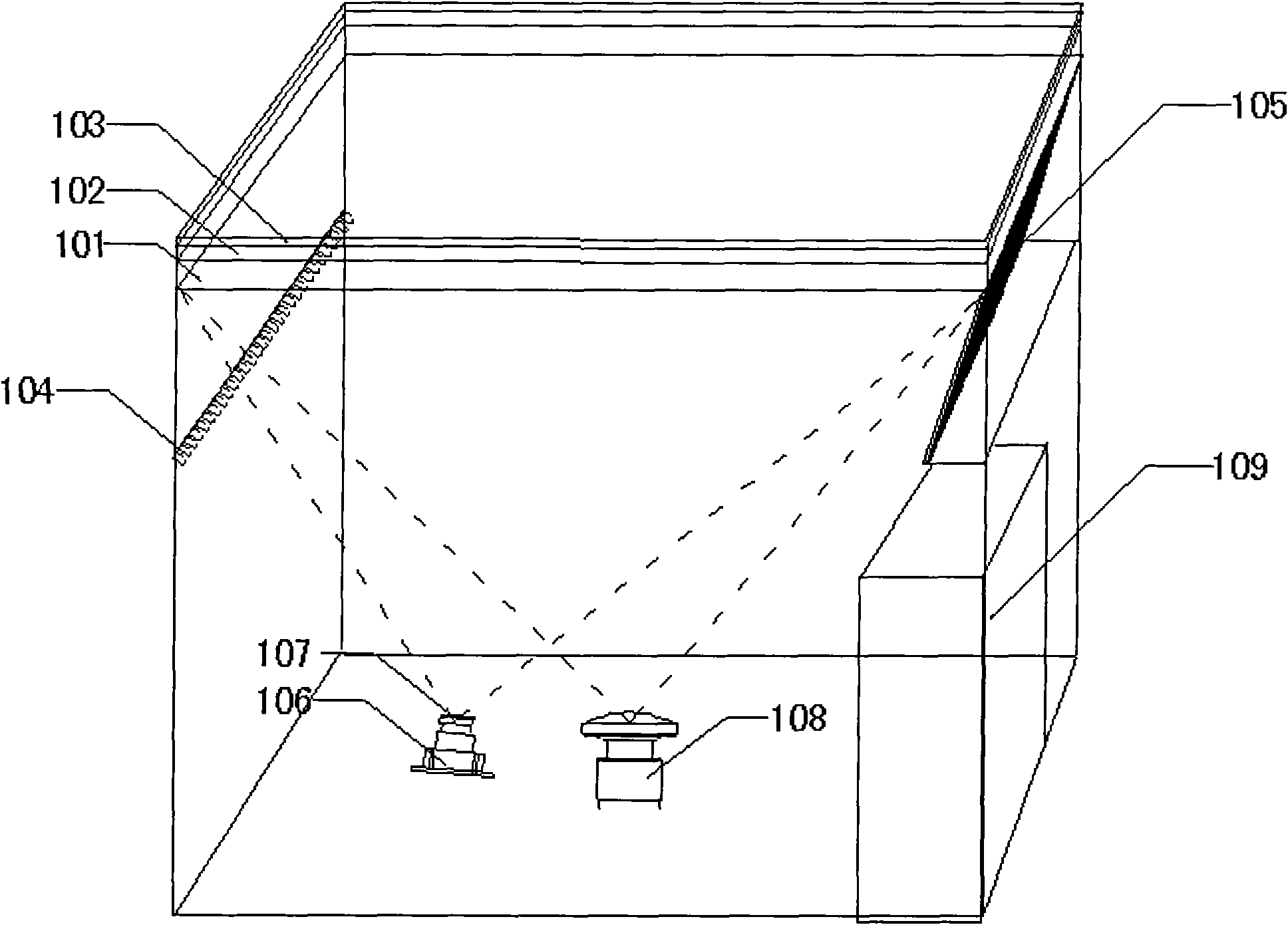
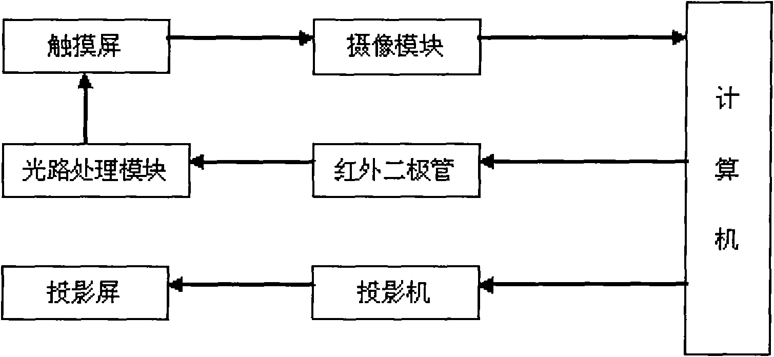
[0050]As a preferred technical solution, the camera-based rear positioning device in this embodiment includes a touch screen, a projection screen, an invisible light emitting module for emitting invisible light onto the touch screen, and a camera module that can photograph the back of the entire touch screen display area , a main control module, a projection module for covering the projection to the entire projection screen, and an optical path processing module for reflecting the invisible light emitted by the invisible light emitting module onto the touch screen.

[0051] like figure 2 Shown is the hardware structure of the device of the present invention, specifically as follows:

[0052] The touch screen includes a touch panel 101 and a protective film 102, the touch panel 101 is made of a material with high light transmission and light guiding performance, and the protective film 102 is attached to the front of the touch panel 101 to block the outside world invisible li...

Embodiment 2

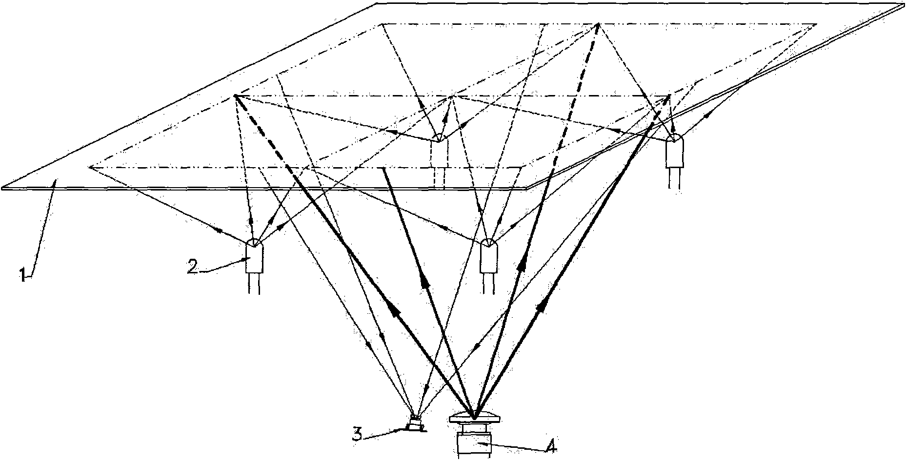
[0077] In this embodiment, in order to increase the light intensity uniformity of infrared light on the entire touch screen, in the post-positioning method based on the camera of the present invention, the invisible light emitting module in step (2) emits infrared light and is incident on the entire touch screen, which can be passed at different times. A new infrared diode is added to the visible light emitting module, and the incident angle of the plane mirror is different from that of the original infrared diode, and the position with the strongest light intensity reflected to the touch screen is the weakest light reflected from the original infrared diode to the touch screen. To achieve light intensity uniformity.

[0078] In this embodiment, the working process of realizing post-positioning based on the camera-based post-positioning device is the same as that of the above-mentioned embodiment 1, and the difference is that, as Figure 7 Shown is a schematic diagram of the o...


PUM


Abstract

The invention provides a post-positioning device and a method based on a pick-up head and an application thereof. The device comprises a touch screen, a projection screen, an invisible light transmission module for transmitting the invisible light to the touch screen, a shooting module shot the back of the whole touch screen display area, a master control module and a projection module covering the projection to the whole projection screen. The projection screen is adhered on the surface of the touch screen. The shooting module is positioned at the back of the touch screen. The projection module is arranged at the back of the projection screen. The master control module is respectively connected with the invisible light transmission module, the shooting module and the projection module. The invention can realize accurate multi-point positioning and is suitable for the post-positioning device of the various touch screens based on the pick-up head.

Description

technical field [0001] The present invention relates to the technical field of interactive electronic display, in particular to a rear positioning device and method based on a camera and its application. Background technique [0002] As a new type of computer input device, the positioning device of the electronic display system makes the human-computer interaction more intuitive. Because it can bring great convenience to the user, the positioning technology of the electronic display system is not only applied to personal portable information products , It has also been used in various fields such as information appliances, public information, electronic games, and office automation equipment. [0003] In the prior art, a multi-touch device positioned by a camera, such as figure 1 As shown, a camera (3), a projector (4), and four backlight sources (2) are arranged below the screen (1), and the monochromatic linear light source of the backlight source (2) is sent to the scree...

Claims


Application Information

Patent Timeline
Patent Type & Authority Applications(China)
IPC IPC(8): G06F3/042
Inventor 刘志文方武平刘小青钟杰婷
Owner GUANGDONG VTRON TECH CO LTD
Why Eureka
Try Eureka