Backlight driving circuit
A technology of backlight drive circuit and electrical connection, which is applied to instruments, static indicators, etc., can solve the problem of high sound wave noise and achieve the effect of reducing sound wave noise
- Summary
- Abstract
- Description
- Claims
- Application Information
AI Technical Summary
Problems solved by technology
Method used
Image
Examples
Embodiment Construction
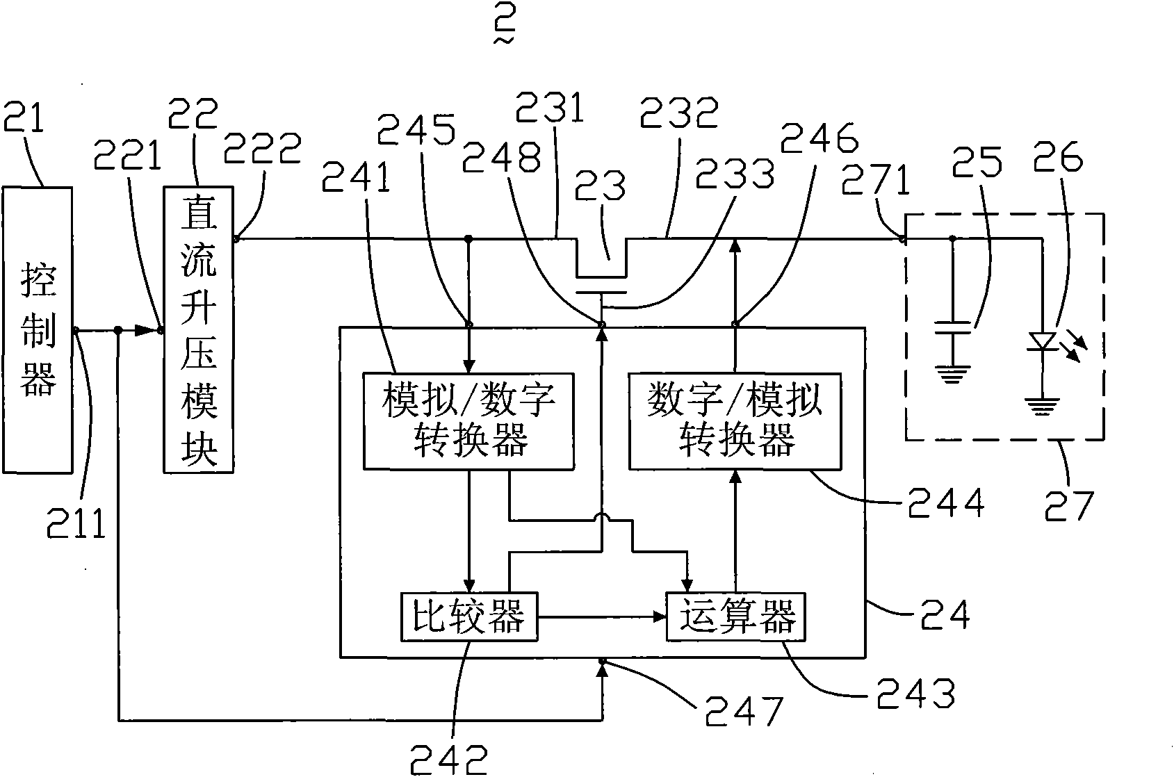
[0013] see figure 2 , is a schematic diagram of the circuit structure of the first embodiment of the backlight driving circuit of the present invention. The backlight driving circuit 2 includes a controller 21 , a DC boost module 22 , a switch assembly 23 , a voltage signal processor 24 and a load 27 .
[0014] The controller 21 includes a control signal output terminal 211 . The controller 21 generates a pulse signal and outputs it from the control signal output terminal 211 .
[0015] The DC boost module 22 includes a control signal input end 221 and an output end 222 . The control signal input end 221 is electrically connected to the control signal output end 211 of the controller 21 .
[0016] The switch element 23 includes a source terminal 231 , a drain terminal 232 and a gate terminal 233 . The source terminal 231 is electrically connected to the output terminal 222 of the DC boost module 22 .
[0017] The load 27 includes a driving voltage input terminal 271 . T...
PUM
 Abstract
Description
Claims
Application Information
 - R&D
- Intellectual Property
- Life Sciences
- Materials
- Tech Scout
- Unparalleled Data Quality
- Higher Quality Content
- 60% Fewer Hallucinations
Browse by: Latest US Patents, China's latest patents, Technical Efficacy Thesaurus, Application Domain, Technology Topic, Popular Technical Reports.
© 2025 PatSnap. All rights reserved.Legal|Privacy policy|Modern Slavery Act Transparency Statement|Sitemap|About US| Contact US: help@patsnap.com


