

Isolating switch
A technology of isolation switch and arc suppression, which is applied in the field of high-voltage switchgear, can solve the problems of weak conversion current capability and contact ablation, and achieve the effect of improving the conversion current capability and reducing the degree of arc ablation
- Summary
- Abstract
- Description
- Claims
- Application Information
AI Technical Summary
Problems solved by technology
Method used
Image

Examples
Embodiment 1
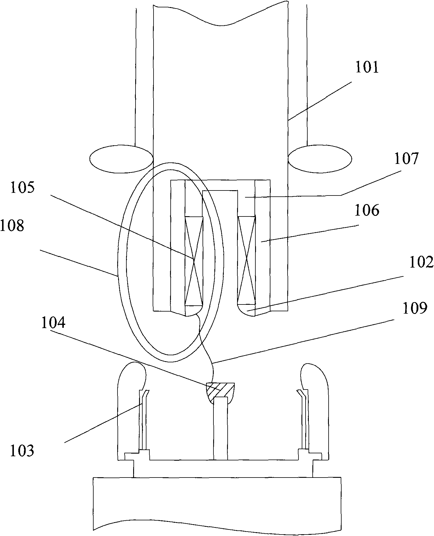
[0027] See figure 1 , the moving contacts in the isolating switch can be composed of moving main contacts 101 and moving arcing contacts 102, and the static contacts can be composed of static main contacts 103 and static arcing contacts 104; coils are installed on the moving arcing contacts 102 105, and set the supporting seat 106 for installing the coil 105, one end of the moving main contact 101 is connected with the mechanism through an insulating pull rod, the other end of the moving main contact 101 is connected with the moving arc contact 102 through the moving end contact seat 107, and the static The main contact 103 and the static arc contact 104 are connected by bolts; the dynamic arc contact 102 and the static arc contact 104 are made of materials resistant to arc ablation, generally copper-tungsten alloy; the coil 105 is made of high heat resistant materials. Generally, copper wire and heat-resistant shrink tube are used.
[0028] The working process of the isolati...
Embodiment 2
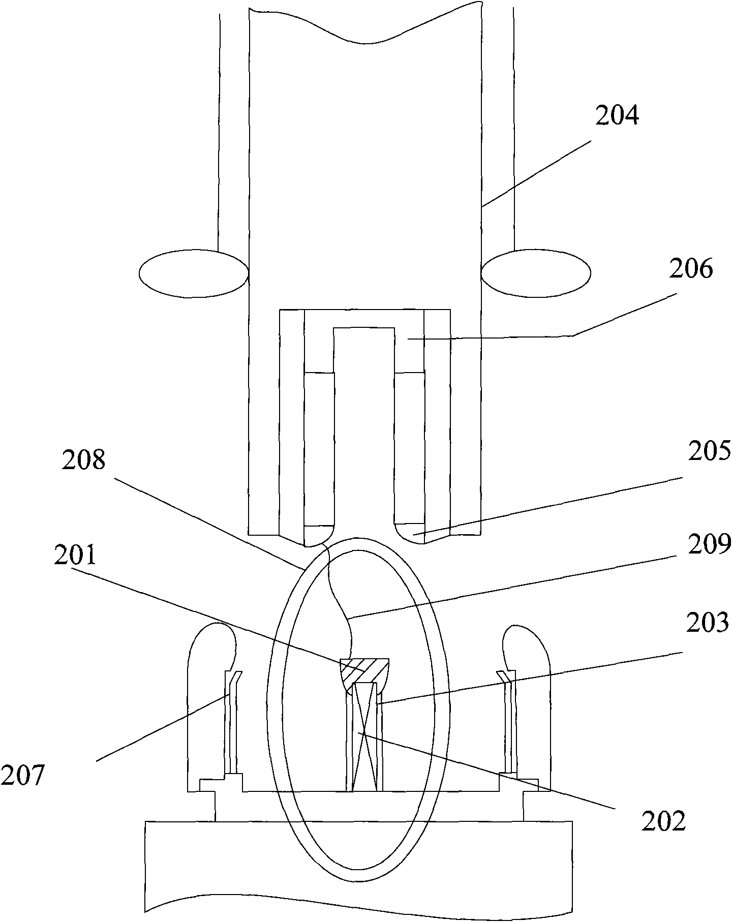
[0031] See figure 2 , install the coil 202 on the static arc contact 201, and set the support seat 203 for installing the coil, one end of the moving main contact 204 is connected with the mechanism through an insulating pull rod, and the other end of the moving main contact 204 and the moving arc contact 205 pass through The moving end contact seat 206 is connected, and the static main contact 207 is connected with the static arc contact 201 through bolts; the moving arc contact 205 and the static arc contact 201 are made of materials resistant to arc ablation, generally copper-tungsten alloy; The coil 202 is made of high heat resistant material, generally copper wire and high heat resistant shrink tube.
[0032] The working process of the isolating switch is as follows:
[0033] When the isolating switch breaks the busbar conversion current, an arc 209 is generated between the moving and static contacts, and the arc current enters the coil to form a magnetic field 208. The...
Embodiment 3
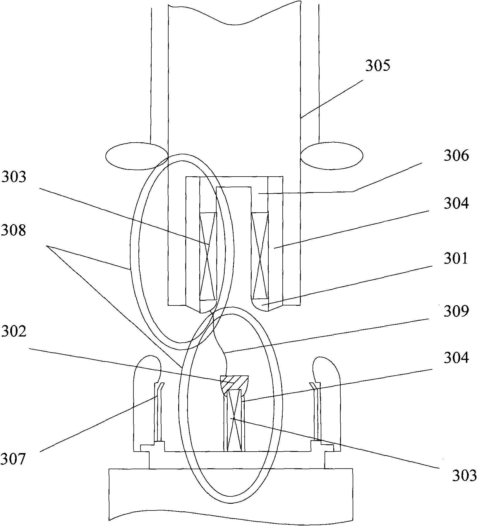
[0035] See image 3 A coil 303 and a support seat 304 are respectively arranged on the moving arc contact 301 and the static arc contact 302, one end of the moving main contact 305 is connected with the mechanism through an insulating pull rod, and the other end of the moving main contact 305 is connected to the moving arc contact 301 is connected through the moving end contact seat 306, and the static main contact 307 is connected with the static arc contact 302 through bolts; the moving arc contact 301 and the static arc contact 302 are made of materials resistant to arc ablation, generally copper tungsten Alloy; the coil 303 is made of high heat-resistant material, generally copper wire and high heat-resistant shrink tube.
[0036] The working process of the isolating switch is as follows:
[0037] When the isolating switch breaks the busbar conversion current, an arc 309 is generated between the moving and static contacts, and the arc current enters the coil to form a mag...
PUM
 Abstract
Description
Claims
Application Information