Vehicular virtual panoramic electronic system

An electronic system, panoramic technology, applied in the direction of closed-circuit television system, etc., can solve the problems of single image, unable to convert the image display effect and mode, without camera image stabilization unit, etc., to achieve the effect of eliminating image offset error

Inactive Publication Date: 2009-11-25
石黎
View PDF2 Cites 44 Cited by
  • Summary
  • Abstract
  • Description
  • Claims
  • Application Information

AI Technical Summary

Problems solved by technology

In both devices, there is no anti-shake unit for the camera image, which cannot solve the video blur caused by the vibration of the vehicle body
At the same time, these two devices have no projection and mapping unit (G),

Method used


Image

  • Vehicular virtual panoramic electronic system
  • Vehicular virtual panoramic electronic system
  • Vehicular virtual panoramic electronic system

Examples


Embodiment Construction

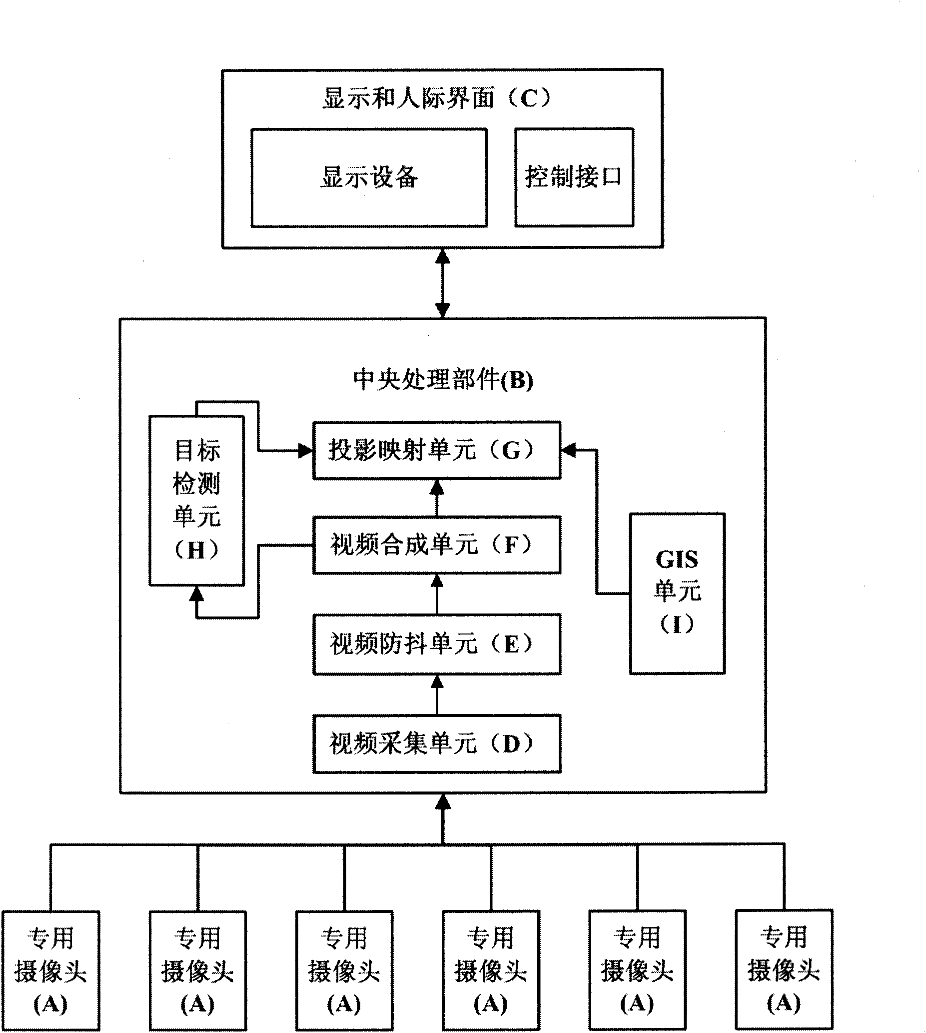
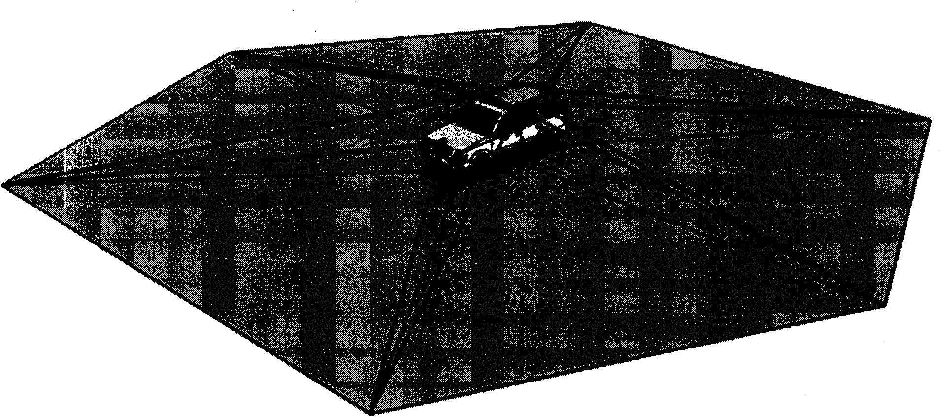
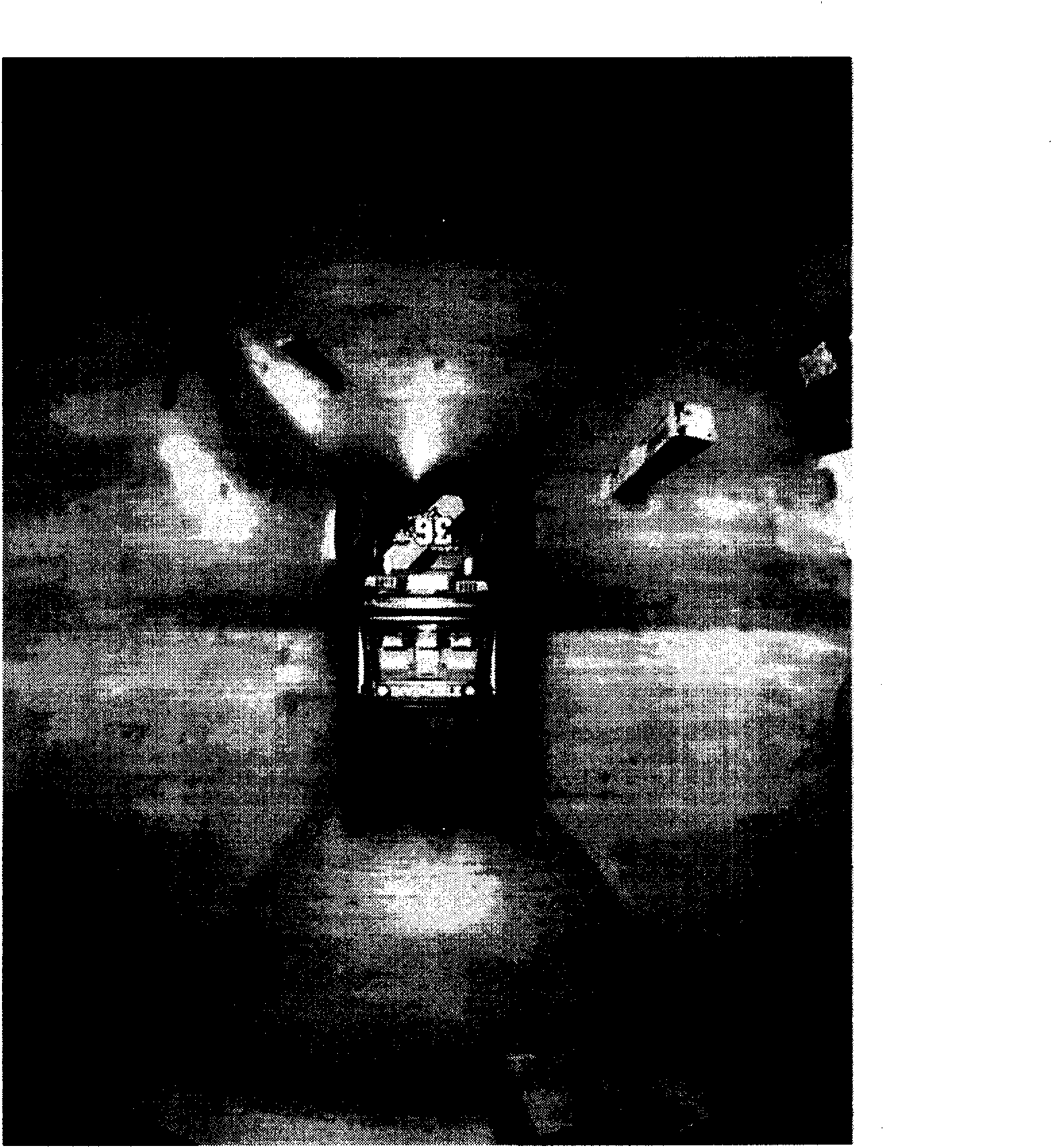
[0027] The solution of the present invention to solve the above problems is that by installing multiple cameras on the hull, car body or equipment, the shooting range of these cameras can completely cover the surrounding environment of the equipment, and by synthesizing the videos taken by these cameras, a panoramic video can be obtained , the field of view of this video is 360 degrees horizontally and 180 degrees vertically, and there is no blind area for the ground range. Then, through the corresponding projection model, the video projection is mapped to the range of the display screen, and the body image is superimposed on the center of the image. The corresponding position, through the use of different projection models, finally provides the driving control personnel with a panoramic view of the fisheye effect, a close-up view without distortion, and images in all directions. Use the requirements of the environment to choose the view mode that meets your needs. At the same...


PUM


Abstract

The invention provides a vehicular virtual panoramic electronic system, mainly comprising a special pick-up head A installed in a distribution type, a central processing unit B and a display and human-machine interface C, wherein the core of the system is the central processing unit including a video collection unit D, a video quiver prevention unit E, a video synthesis unit F, a projection and mapping unit G, a target detection unit H and a GIS unit I. The invention implements the seamless splicing to the video image collected by the special pick-up head A installed in a distribution type based on the ground by the video synthesis unit F, thus achieving a single real time panoramic video which can cover the whole range around the vehicle body without a blind zone and is converted into various effects to be displayed on the display and human-machine interface C by the projection and mapping unit G. Meanwhile, the target detection unit H can actively identify the periphery vehicles and travelers. The map information of the GIS unit I can be displayed in a way that is overlapped with the real time video, thereby providing an all-directional virtual panoramic real time video, and the integrated obstruction prewarning and navigation information for the vehicle drive operating staff.

Description

technical field [0001] The present invention relates to an electronic system for providing image information for driving assistance. Background technique [0002] Due to the existence of visual blind spots when driving a vehicle, the driver cannot completely truly and accurately understand the position and distance relationship between the car body and the surrounding environment, which often leads to some accidents. In mining and other fields, the length and width of large-scale construction machinery and large-scale transport vehicles used are about several meters to ten meters, or even tens of meters. The field of vision of the driver and operator is even more limited. environment, accidents are more frequent due to blind spots of driving operators. [0003] Fundamentally, solving this kind of problem is to make up for the visual blind spots through some kind of sensor signal. Existing solutions include the use of Doppler radar, ultrasonic waves, radio frequency signal ...

Claims


Application Information

Patent Timeline
IPC IPC(8): H04N7/18
Inventor 石黎
Owner 石黎
Why Eureka
Try Eureka