Sheet-feed printer

A printing machine and single-page technology, applied in the direction of printing machines, printing, general parts of printing machinery, etc.

Inactive Publication Date: 2009-11-25
MITSUBISHI HEAVY IND LTD
View PDF2 Cites 0 Cited by
  • Summary
  • Abstract
  • Description
  • Claims
  • Application Information

AI Technical Summary

Problems solved by technology

[0012] This becomes a big problem when guiding a single page with a printing surface that is not sufficiently dried on the lower side, such as double-sided printing.

Method used


Image

  • Sheet-feed printer
  • Sheet-feed printer
  • Sheet-feed printer

Examples


no. 1 example

[0074] Use the following Figure 1 to Figure 7 A first embodiment of the present invention will be described.

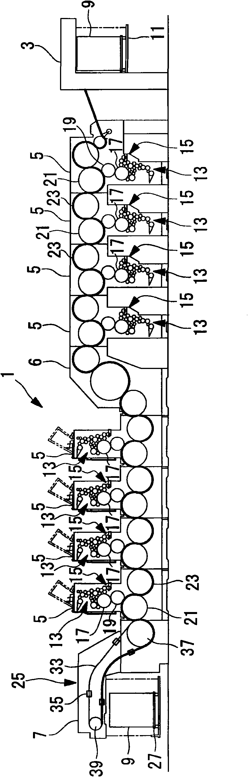
[0075] figure 1 It is a front view showing an overall schematic configuration of a double-sided printing machine (single-sheet printing machine) 1 .

[0076] The single-sheet double-sided printing machine 1 is equipped with: a sheet feeding device 3 that supplies the stacked single sheets from the upstream side to the downstream side of the single sheets that are supplied to the printed matter; for example, a plurality of printing units 5 that print different colors to realize color printing; The paper discharge device 7 where the single sheets are placed in a stacked state.

[0077] The paper feeding device 3 sequentially takes out and supplies the single sheets 9 stacked on the paper feeding table 11 one by one from the top using a paper feeding mechanism (sheet sucker, cam, etc.) not shown.

[0078] The paper feed table 11 moves upward in response to feeding of...

no. 2 example

[0181] Use below Figure 9 with Figure 10 A second embodiment of the present invention will be described.

[0182] The basic structure of this embodiment is the same as that of the first embodiment, but the structure of the cavity 57 is different. This difference will be described in this embodiment, and repeated descriptions of other parts will be omitted.

[0183] The same symbols are assigned to the same structural elements as those in the first embodiment, and detailed description thereof will be omitted.

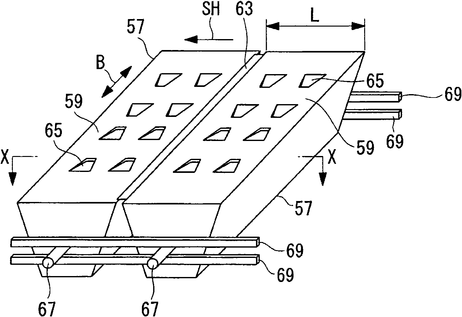
[0184] Figure 9 It is a front view showing a part of the moving sheet guide 43 . Figure 10 is a front view of cavity 58.

[0185] When the moving single-sheet guide 43 is moved in the single-sheet conveyance direction SH corresponding to the size of the single sheet 9, the moving single-sheet guide 43 has a cavity 58 that can be positioned at the convexly curved portion 53 and a cavity that cannot be positioned at the convexly curved portion 53. Cavity 57.

[...

no. 3 example

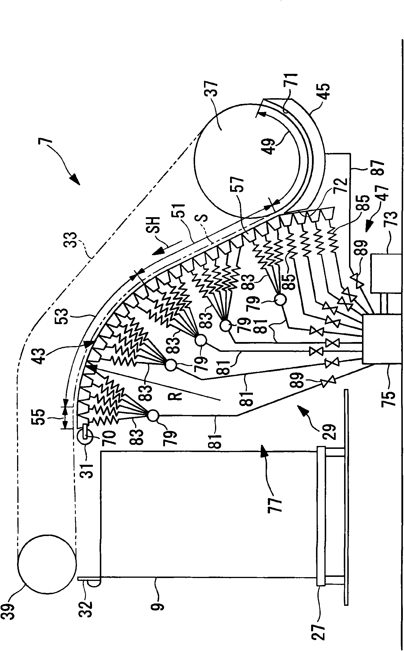
[0194] Use below Figure 11 A third embodiment of the present invention will be described.

[0195] The basic structure of this embodiment is the same as that of the first embodiment, but the structure of the cavity 57 is different. This difference will be described in this embodiment, and repeated descriptions of other parts will be omitted.

[0196]The same symbols are assigned to the same structural elements as those in the first embodiment, and detailed description thereof will be omitted.

[0197] Figure 11 It is a front view showing a part of the moving sheet guide 43 .

[0198] When the moving sheet guide 43 moves in the sheet conveyance direction SH corresponding to the size of the sheet 9, the upstream side portion of the moving sheet guide 43 has a cavity 56 that can be located at a part away from the sheet conveyance path S and It is impossible to locate the cavity 57 at the part away from the sheet conveyance path S. As shown in FIG.

[0199] In this embodime...


PUM


Abstract

A sheet-feed printer which can convey a printed sheet surely in a stable posture without causing undulation even if sheets of a variety of sizes are employed. The perfecting sheet-feed printer (1) comprises a sheet guide (29) having an air ejection nozzle (65) in the guide surface (59) and guiding a sheet (9) conveyed while being gripped by a gripper (35), and a vacuum suction wheel (31) disposed on the downstream side of the sheet guide (29) in the conveying direction of sheet and applying a brake to the sheet (9). The sheet guide (29) comprises a moving sheet guide portion (43) movable in the conveying direction of sheet and having a part for forming the downstream side portion in the conveying direction of sheet, and a fixed sheet guide portion (45) forming the upstream side portion in the conveying direction of sheet. The moving sheet guide portion (43) is constituted of a chamber (57) divided into a plurality of sections in the conveying direction of sheet such that each section has the air ejection nozzle (65) and adjoining sections are coupled to be bent freely.

Description

technical field [0001] This invention relates to cut-sheet printing presses. Background technique [0002] In the sheet discharge device of a cut-sheet printing machine, the front end of the printed sheet is caught by the nipper device before the printing surface is sufficiently dry, so there is a tendency for the entire sheet to fluctuate greatly as it travels. [0003] Due to its ups and downs, the single page is in contact with the surrounding parts and rubbed, which may cause the single page or its printing surface to be scratched and soiled. [0004] In order to prevent this and convey a single page in a stable posture, there are various proposals (for example, Patent Document 1, Patent Document 2). [0005] Patent Document 1 shows that guides are provided below the single sheet conveying path along the entire surface along the bottom, and the single sheet is aligned while suppressing the downward movement of the single sheet by using the air existing between the guide...

Claims


Application Information

Patent Timeline
Patent Type & Authority Applications(China)
IPC IPC(8): B41F21/00B65H29/52
CPCB65H29/041B65H29/52B41F21/00B65H2406/113
Inventor 山本修西井裕也
Owner MITSUBISHI HEAVY IND LTD
Why Eureka
Try Eureka