Clamping device for rail butt welding

A technology for clamping devices and rails, applied in auxiliary devices, welding equipment, auxiliary welding equipment, etc., can solve the problems of increasing the force of the clamping cylinder 4, increasing the weight or height of the whole machine, etc., to ensure vertical positioning, reduce the Effect of wear and simplification of structure

Active Publication Date: 2011-11-16
成都瑞威交通科技有限公司
View PDF0 Cites 0 Cited by
  • Summary
  • Abstract
  • Description
  • Claims
  • Application Information

AI Technical Summary

Problems solved by technology

However, due to the size of the rotating shaft 5 itself and the limitation of the required installation size of the clamp 1 and the position of the rail, the distance between the central axis 5 and the clamping jaw 7 is relatively large, that is, the force-applying arm a and the force-receiving arm in the figure The ratio a / b of b is not large
If a relatively large clamping force is to be obtained, either the upper arm of the clamp 1 is lengthened, or the force of the clamping cylinder 4 is increased. Obviously, both of them need to increase the weight or height of the whole machine, which is very important for the use in construction. On-site mobile rail welding machines are all unfavorable factors

Method used


Image

  • Clamping device for rail butt welding
  • Clamping device for rail butt welding
  • Clamping device for rail butt welding

Examples


Embodiment 1

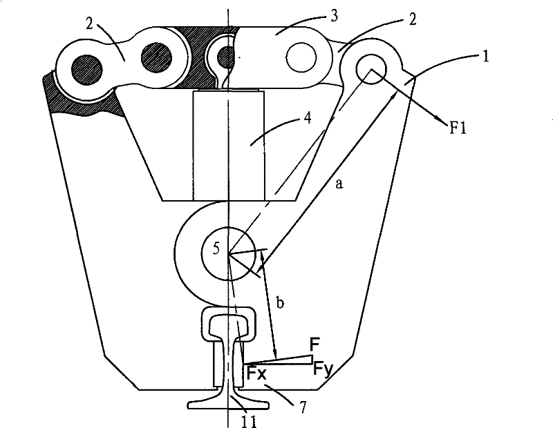
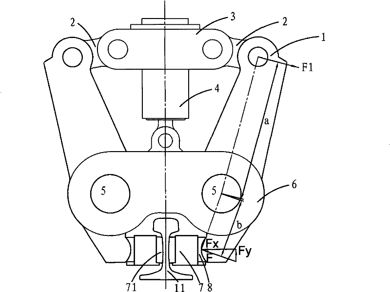
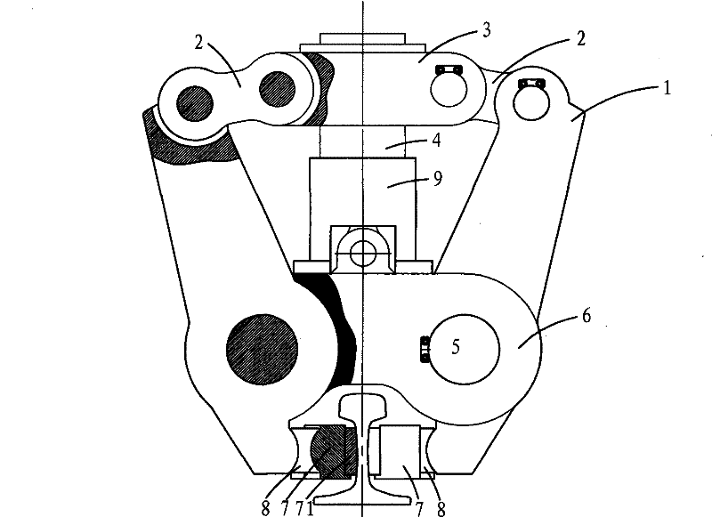
[0033] Embodiment 1: as figure 2 , image 3 , Figure 4 and Figure 5 As shown, on the basis of the prior art, the single-axis rotation structure of the jaws in the prior art is improved to a double-axis rotation structure of the jaws, so that the center of the rotation axis is lowered, and a higher clamping force magnification is obtained. ; Simultaneously, since the center of rotation is respectively located on both sides of the rail, the clamps apply a horizontal clamping force and a vertical upward lifting force to the rail at the same time, so there is no need to set up a rail lifting mechanism, thereby simplifying the structure. The specific scheme is: a clamping device for rail butt welding, including two pairs of clamps 1, clamping jaws 7, a clamp applying mechanism, and two rotating shafts 5; the clamp applying mechanism includes connecting rods 2 , Clamping oil cylinder support 3 and clamping oil cylinder 4, clamping oil cylinder 4 is installed vertically, its tw...

Embodiment 2

[0038] Embodiment 2: as Figure 9 and 10 As shown, the main difference between Embodiment 2 and Embodiment 1 lies in the difference of the clamp applying mechanism. The clamp applying mechanism in this embodiment includes a transverse connecting rod 21, clamping oil cylinder transverse supports 31, 32 and clamping Oil cylinder 4, the clamping oil cylinder 4 is installed horizontally, and its two ends are respectively connected with clamping oil cylinder transverse supports 31, 32, and the upper end of the clamp 1 is connected with the clamping oil cylinder transverse supports 31, 32 through transverse connecting rod 21 32 active connections.

Embodiment 3

[0039] Embodiment 3: as Figure 11 As shown, the main difference between Embodiment 3 and Embodiment 1 lies in the difference of the clamp force applying mechanism. The clamp force applying mechanism in this embodiment includes a clamping oil cylinder 4, which is installed horizontally, and its two ends are respectively There is a hinge seat, and the upper end of the jaw 1 is directly connected to the hinge seats at both ends of the clamping cylinder 4 movably.


PUM


Abstract

The invention discloses a clamping device for rail butt welding, which comprises pliers clips (1), a pliers-clip force application mechanism, rotating shafts (5) and clamping jaws (7), wherein the upper ends of the pliers clips (1) are movably connected with the pliers-clip force application mechanism. The clamping device is characterized in that the lower part of the pliers-clip force application mechanism also comprises a pliers-clip support (6); two rotating shafts (5) are arranged on two sides of the pliers-clip support (6) respectively according to the direction parallel to the length ofrails; at least one pair of pliers clips (1) is connected together with the pliers-clip support (6) through the rotating shafts (5); and the lower ends of the pliers clips (1) are connected with the clamping jaws (7) so as to form a lever structure which takes the rotating shafts (5) as fulcrums, takes the upper ends of the pliers clips (1) as force application points and takes the lower ends of the pliers clips (1) as force bearing points. The clamping device has the advantage of obtaining large clamping force under the condition of not increasing the height of a machine.

Description

technical field [0001] The invention belongs to the technical field of on-site rail welding equipment for railway seamless lines, and in particular relates to a clamping device of a mobile rail butt welding machine. Background technique [0002] In the laying construction of seamless lines, on-site welding of steel rails is required. The welding methods currently used are mainly flash welding and pressure welding. Mobile flash rail welding machines are mainly produced by European and American countries, with a high degree of automation, while pneumatic rail welding machines are all small machines that are mainly manual operations. In the rail butt welding process, whether flash welding or gas pressure welding is used, the two ends of the joint to be welded need to be clamped and aligned, and then heated and upset. Due to the large cross-sectional area and high strength of the rail, the required upsetting force plus pre-tensioning force during welding is more than 100 tons....

Claims


Application Information

Patent Timeline
Patent Type & Authority Patents(China)
IPC IPC(8): B23K37/053
Inventor 黄正中
Owner 成都瑞威交通科技有限公司
Why Eureka
Try Eureka