Two-stage drive shaft device

A technology of drive shaft and sliding device, which is applied in the direction of control device, transportation and packaging, vehicle parts, etc., can solve the problems of vehicle wheel elevation, hidden danger, insufficient slip margin, etc. The effect of increasing adaptability

Active Publication Date: 2009-12-02
SUZHOU AUTO TECH
View PDF0 Cites 5 Cited by
  • Summary
  • Abstract
  • Description
  • Claims
  • Application Information

AI Technical Summary

Problems solved by technology

[0005] Under the normal driving conditions of the car, the traditional drive shaft can meet the movement requirements of the wheels only through the slippage of the sliding joint, but cannot meet the large-scale movement requirements of the wheels.
For example, desert vehicles often encounter high sand dunes, which cause the wheels of the vehicle to be greatly raised. At this time, ordinary sliding joints cannot meet the movement requirements of the wheels. A series of potential safety hazards caused by insufficient slip margin

Method used


Image

  • Two-stage drive shaft device
  • Two-stage drive shaft device
  • Two-stage drive shaft device

Examples


Embodiment Construction

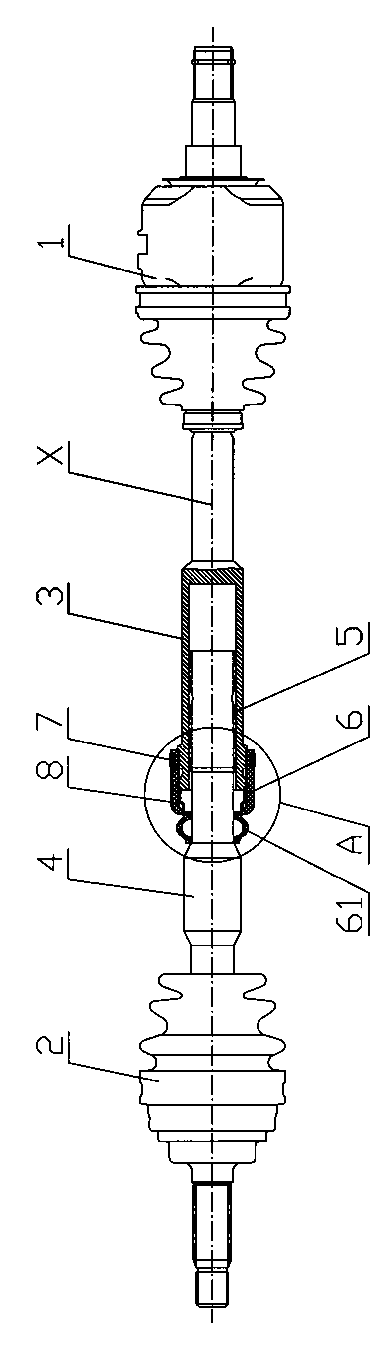
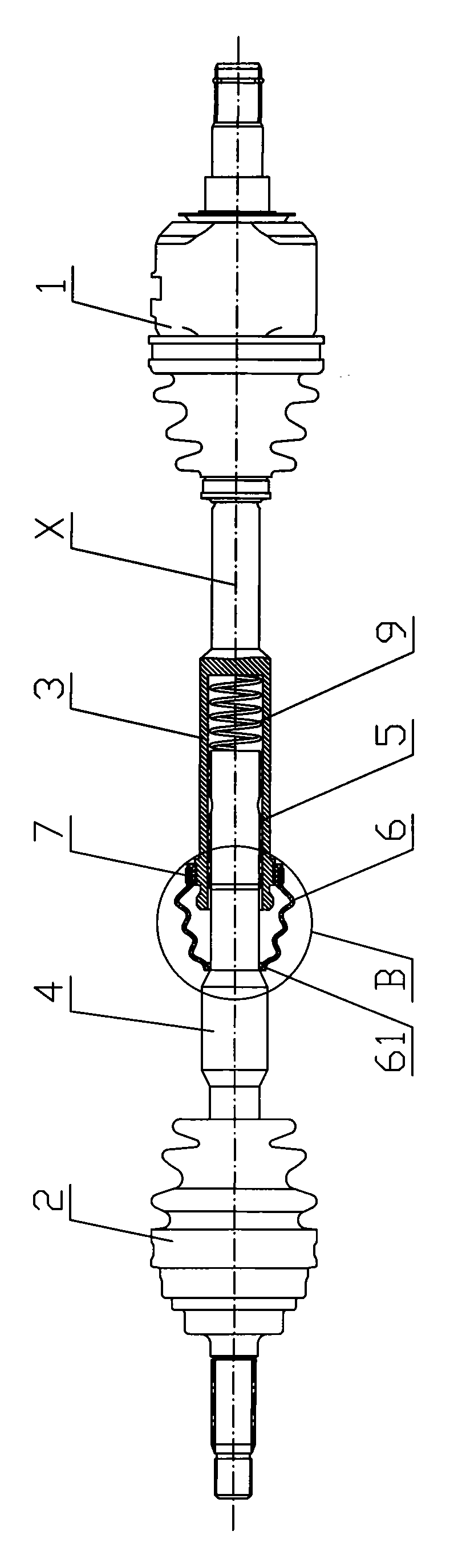
[0027] The invention discloses a two-stage drive shaft device, such as figure 1 and image 3 The first embodiment shown includes a sliding joint 1 whose shaft is connected to the transmission and a fixed joint 2 whose shaft is connected to the wheel hub. Both the sliding joint 1 and the fixed joint 2 adopt the constant velocity universal joint of the prior art Yes, that is, the sliding joint itself can slide and expand along its axial direction X to compensate for changes in the axial length of the drive shaft.

[0028] The improvement point of the present invention is that, instead of the rigid connection between the sliding joint 1 and the fixed joint 2 in the prior art, a two-stage joint for adjusting the relative axial distance between the sliding joint and the fixed joint is provided. Auxiliary slide.

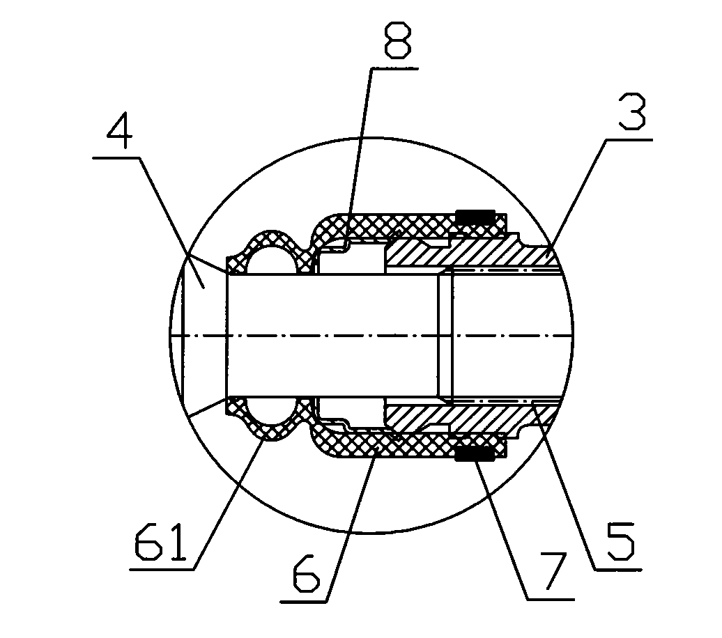
[0029] Specific reference figure 1 and image 3 As shown, the secondary auxiliary sliding device includes a shaft sleeve 3 fixed at one end of the sliding joint 1 and ...


PUM


Abstract

The invention provides a two-stage drive shaft device, which comprises a slip joint and a fixed joint. The slip joint is connected to a speed changer through a shaft, the fixed joint is connected to a wheel hub through the shaft, and a secondary auxiliary slip device used for adjusting the relative axial distance of the slip joint and the fixed joint is arranged between the slip joint and the fixed joint. The two-stage drive shaft device has the following main advantages: (1) the prior fixed joint and the slip joint are not changed; (2) the secondary auxiliary slip device is used for making up the problem that the slip amount of the slip joint end of a driving shaft is deficient due to large motion range of the driving shaft in various limit running conditions of a vehicle; and (3) the two-stage drive shaft device has a simple and reliable structure, and is applicable for the vehicles similar to desert trucks and the like which always run under the limit working conditions.

Description

technical field [0001] The invention relates to a drive shaft and belongs to the technical field of automobiles. Background technique [0002] The drive shaft is mostly used in front-wheel drive vehicles. In addition to transmitting the power from the gearbox to the left and right front wheels, it also needs to cooperate with the change of the steering angle. The drive shaft assembly includes a rotating shaft that transmits torque, one end of which is connected to a sliding joint, and the other side of the sliding joint is connected to the transmission; the other end of the rotating shaft is connected to a fixed joint, and the other side of the fixed joint is connected to the transmission. on the wheel hub. [0003] The power of a front-wheel drive vehicle is directly transmitted to the front wheels through the sliding joint, the rotating shaft, and the fixed joint from the power assembly composed of the engine, transmission and final drive. Since the front wheel is both a...

Claims


Application Information

Patent Timeline
Patent Type & Authority Applications(China)
IPC IPC(8): B60K17/22
Inventor 宿佳敏王凯田永义宋峰宋茂志李明李宏声徐业苍林引婵刘斌束永福
Owner SUZHOU AUTO TECH
Why Eureka
Try Eureka