Yarn cutter for clearing winding yarn

A technology of cutting and wrapping yarn, applied in textile and papermaking, weft knitting, knitting and other directions, can solve the problems of blade cuts, affecting the coiling of the coiling mechanism, affecting the pulling force of the knitted fabric, etc.

Inactive Publication Date: 2011-02-02
JIANGSU JINLONG TECHNOLOGY CO LTD
View PDF0 Cites 0 Cited by
  • Summary
  • Abstract
  • Description
  • Claims
  • Application Information

AI Technical Summary

Problems solved by technology

However, due to static electricity, during the movement of a pair of cloth sleeves 4, the yarn from the braid will appear to be entangled on the surface of the cloth sleeve 4, which must be cleaned in time, otherwise it will affect the traction of the braid The pulling force of the device on the braid affects the winding of the subsequent winding mechanism
[0004] In the prior art, the following methods are usually used to clean the yarn entangled on the cloth cover 4. One is to cut the yarn with a double-sided blade (shaving utensil) used in daily life or use a single-sided blade to cut the yarn. The yarn is cut, and then the cut yarn is removed. Practice has proved that this cleaning method is more effective. However, the probability of the blade cutting the cloth cover 4 is extremely high, leaving numerous scars on the surface of the cloth cover 4. , affect the service life and increase the frequency of replacement; the second is to clean it by hand without borrowing any tools. Although this cleaning method will not damage the cloth cover, it is troublesome to clean because it is difficult for the cleaner's fingers to penetrate into a In the gaps between the cloth-holding sleeves 4, the yarns can only be broken and removed one by one on the top of the cloth-holding sleeves 4. It can be seen that the cleaning efficiency is low, and there is also the problem of incomplete cleaning.

Method used


Image

  • Yarn cutter for clearing winding yarn
  • Yarn cutter for clearing winding yarn
  • Yarn cutter for clearing winding yarn

Examples


Embodiment 1

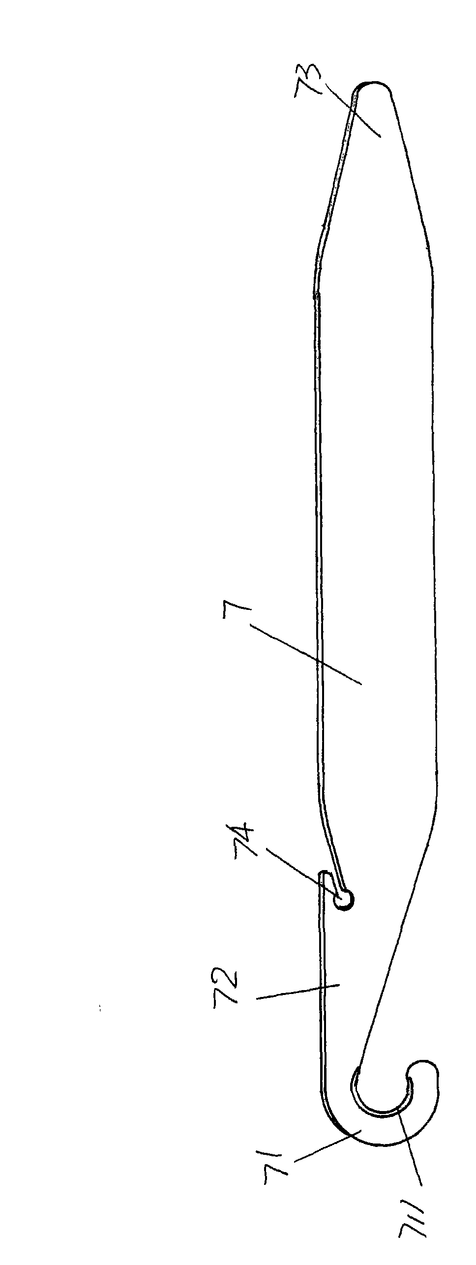
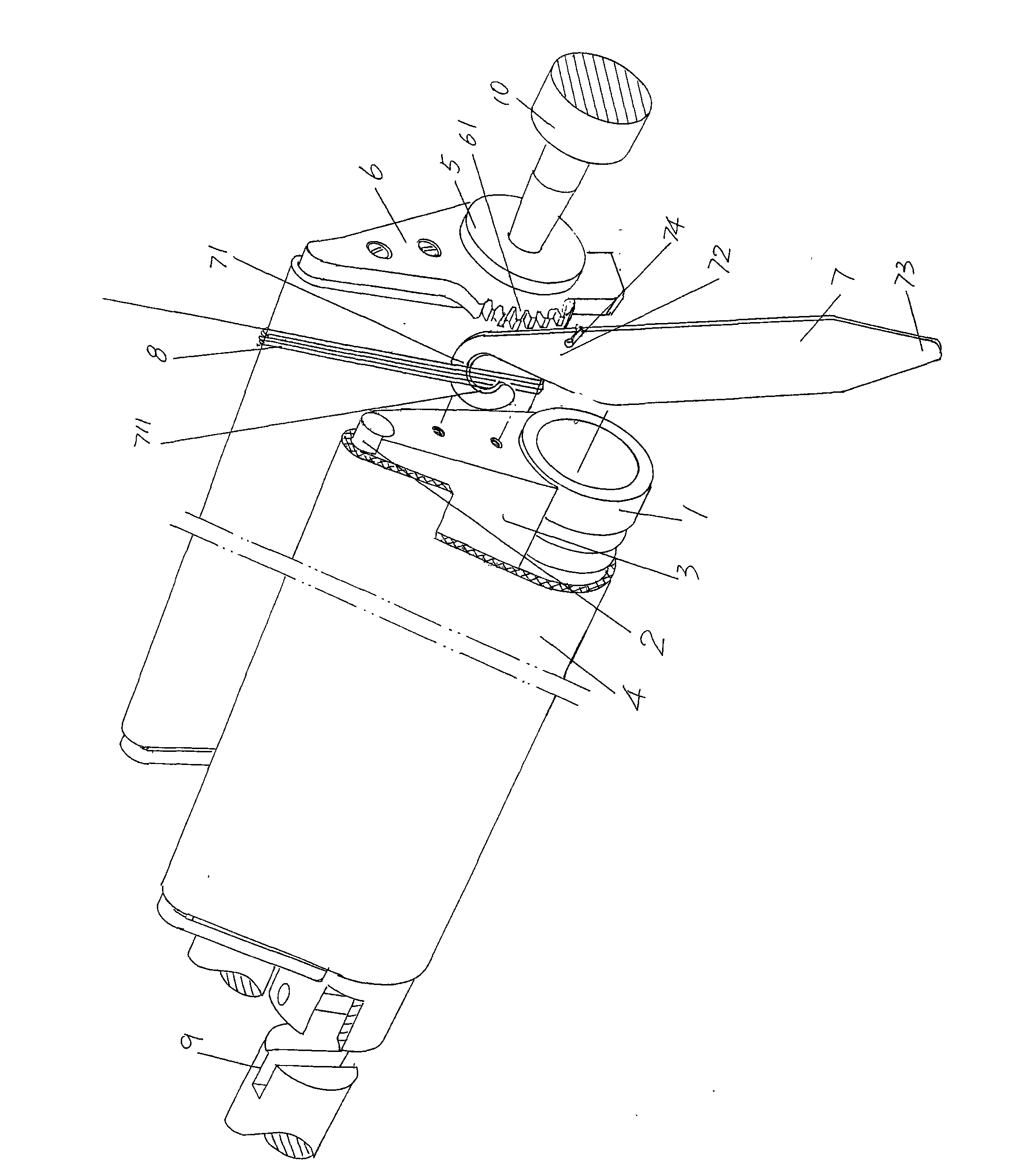
[0019] please see figure 1 , provides a knife bar 7 whose material is preferably made of stainless steel, the knife bar 7 is flat and elongated, and one end of the knife bar 7 is currently figure 1 The left end of the shown position state forms a narrow body 72 whose width is obviously smaller than the middle part of the knife bar 7, that is to say, one end of the knife bar 7 forms a narrow body 72 with a width narrower than the width of the middle part, and the end of the narrow body 72 is bent And constitute cutter head 71, in the present embodiment, the bending of the end of narrow body 72 is U-shaped bending, and the cutting edge 711 on the cutter head 71 is positioned at U-shaped cavity, that is to say, because cutter head 71 It is U-shaped, so the yarn cutting blade 711 is also U-shaped. Form a hanging groove 74 at the junction of the aforementioned narrow body 72 and the cutter bar 7, that is, the junction. At the other end of the knife bar 7 that is figure 1 The ...

Embodiment 2

[0021] The figure is omitted, only the shape of the cutter head 71 is changed into a 7-shape, and the yarn cutting blade 711 is located on the inside of the 7-shape. This scheme is essentially to form the cutter head 71 into a sickle-like effect, that is, in the shape of a sickle. All the other are the same as the description to embodiment 1.


PUM


Abstract

The invention provides a yarn cutter for clearing winding yarn, and belongs to the technical field of auxiliary tools of knitting machines. The yarn cutter comprises a cutter rod; one end of the cutter rod forms a bended cutter head; and the cutter head is provided with a yarn cutting edge. The yarn cutter has the advantages that the yarn cutter can conveniently cut waste yarn wound on a cloth clamping sleeve, and the cloth clamping sleeve is not damaged when the waste yarn is cut.

Description

technical field [0001] The invention belongs to the technical field of auxiliary tools for knitting machines, and in particular relates to a yarn cutter for clearing entangled yarns, which is used to clean the yarns entangled on the surface of the cloth-holding sleeve of a braided fabric traction device of a computerized flat knitting machine. Background technique [0002] On the flat knitting machine, especially the computerized flat knitting machine, it is necessary to configure the sub-roller mechanism. It is as close as possible to the cylinder mouth, that is to say, its position is required to be higher. In view of this, the industry also calls the secondary roller mechanism a high roller mechanism. The auxiliary roller mechanism has a pair of braid pulling devices. Figure 4 Shown is one of the structural forms of the braid pulling device in the prior art, including a pair of configurations and each having a roller 1, a transition bar 2, a transition bar support member...

Claims


Application Information

Patent Timeline
Patent Type & Authority Patents(China)
IPC IPC(8): D04B35/32D04B15/90
Inventor 金永良张和中海港兰先川
Owner JIANGSU JINLONG TECHNOLOGY CO LTD
Why Eureka
Try Eureka