Fixing method with self-lock nut supporting plate and rivet free supporting plate self-lock nut

A technology of self-locking nuts and fixing methods, applied in the direction of nuts, threaded fasteners, connecting components, etc., can solve the problems of not being able to install on arc surfaces, increasing installation difficulty, and time-consuming and laborious installation, so as to improve fatigue life, The effect of long service life and low cost of use

Inactive Publication Date: 2009-12-02
GUIZHOU AEROSPACE PRECISION PRODS
View PDF6 Cites 2 Cited by
  • Summary
  • Abstract
  • Description
  • Claims
  • Application Information

AI Technical Summary

Problems solved by technology

This existing fixing method not only has the disadvantages of many types of tools required for installation, time-consuming and laborious installation, and inconvenient installation, but also has the disadvantage that the self-locking nut with the lug plate can only be installed on a plane. The disadvantage that it cannot be installed on the arc surface; in addition, the self-locking nut with the lug plate is fixed on the aircraft structure by rivets. It is required that the hole distance error of the installation hole of the double-sided laminate is very small during installation, and the error is too large to cause the same When the bolts are matched, they cannot be assembled if they are dislocated, which greatly increases the requirements for the hole-making accuracy during installation, thus increasing the difficulty of installation.

Method used


Image

  • Fixing method with self-lock nut supporting plate and rivet free supporting plate self-lock nut
  • Fixing method with self-lock nut supporting plate and rivet free supporting plate self-lock nut
  • Fixing method with self-lock nut supporting plate and rivet free supporting plate self-lock nut

Examples


Embodiment Construction

[0014] The present invention will be further described in detail below in conjunction with the accompanying drawings and embodiments, but it is not used as a basis for any limitation of the present invention.

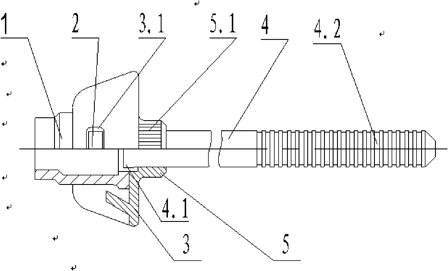
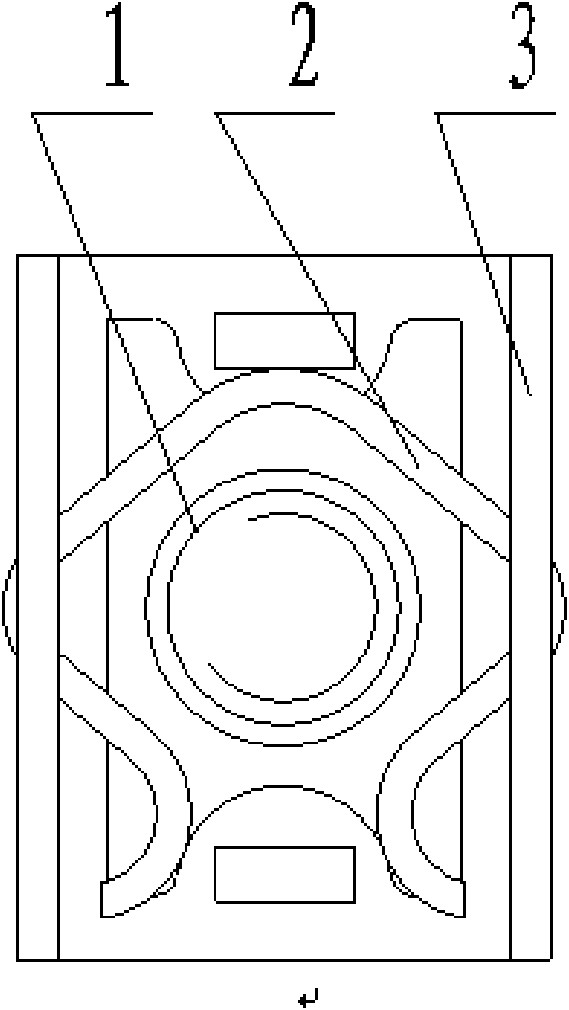
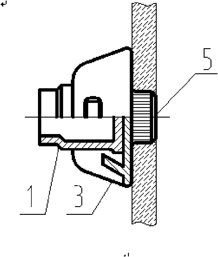
[0015] Embodiment of the present invention: when fixing the supporting plate with the self-locking nut on the structural parts that need to be connected, a fixing method of the supporting plate with the self-locking nut of the present invention is adopted for implementation, that is, the supporting plate with the self-locking nut is first fixed on the supporting plate. Make a boss protruding from the bottom surface of the pallet and have a through hole on the board, then pass a pull rod through the through hole of the boss of the pallet, and make a section of tapered cylinder at one end of the rod, so that the The diameter of the tapered cylinder is larger than the diameter of the through hole of the boss of the supporting plate, and then the boss of the supporting plate...


PUM


Abstract

The invention discloses a fixing method for a self-lock nut supporting plate and a rivet free supporting plate self-lock nut. When a supporting plate with a self-lock nut is fixed on a structural member needing the connection, firstly, the supporting plate is provided with a lug boss for protruding a bottom surface of the supporting plate and with a through hole; secondly, a pull rod of a cylinder with taper passes through the through hole of the lug boss; the pull rod is pulled by a pull gun to pass through the through hole of the lug boss, so that the lug boss part of the supporting plate expands to the surrounding and is embedded into the structural member; and finally, a supporting plate component with a self-lock nut is fixed on the structural member. The fixing method for the self-lock nut supporting plate and the rivet free supporting plate self-lock nut not only have the advantages of improving the mounting speed and the reliability, and enlarging the sandwich range and the mounting position, but also has light weight, compact design and the reduction of using cost; a mounting plate is free from counter sinking, scratching nest and chamfering, and can be arranged on a plane, an inclined surface and an arc surface; and the self-lock nut is moveably connected with an airplane structural member, can be changeable and has longer service life.

Description

technical field [0001] The invention relates to a fixing method for a support plate with a self-locking nut used for single-sided connection of plates and a self-locking nut for a rivetless support plate, belonging to the technical field of plate connection. Background technique [0002] At present, when planes need to connect plates with self-locking function, the connection method of self-locking nuts with lug plates is generally used. The first is the installation and fixing hole of the self-locking nut of the lug plate, and the lug plate and the plate need to be connected by rivets, so that the self-locking nut of the lug plate is fixed on the aircraft structure. This existing fixing method not only has the disadvantages of many types of tools required for installation, time-consuming and laborious installation, and inconvenient installation, but also has the disadvantage that the self-locking nut with the lug plate can only be installed on a plane. The disadvantage tha...

Claims


Application Information

Patent Timeline
Patent Type & Authority Applications(China)
IPC IPC(8): F16B37/04
Inventor 唐伟刘敏丽
Owner GUIZHOU AEROSPACE PRECISION PRODS
Why Eureka
Try Eureka