Actuator apparatus and image pickup unit
A technology for a camera unit and a moving lens, which is applied in the fields of instruments, optical components, medical science, etc., can solve the problems of hindering the optical characteristics of the camera unit, and the moving lens frame cannot move forward and backward stably.
- Summary
- Abstract
- Description
- Claims
- Application Information
AI Technical Summary
Problems solved by technology
Method used
Image


Examples
no. 1 approach
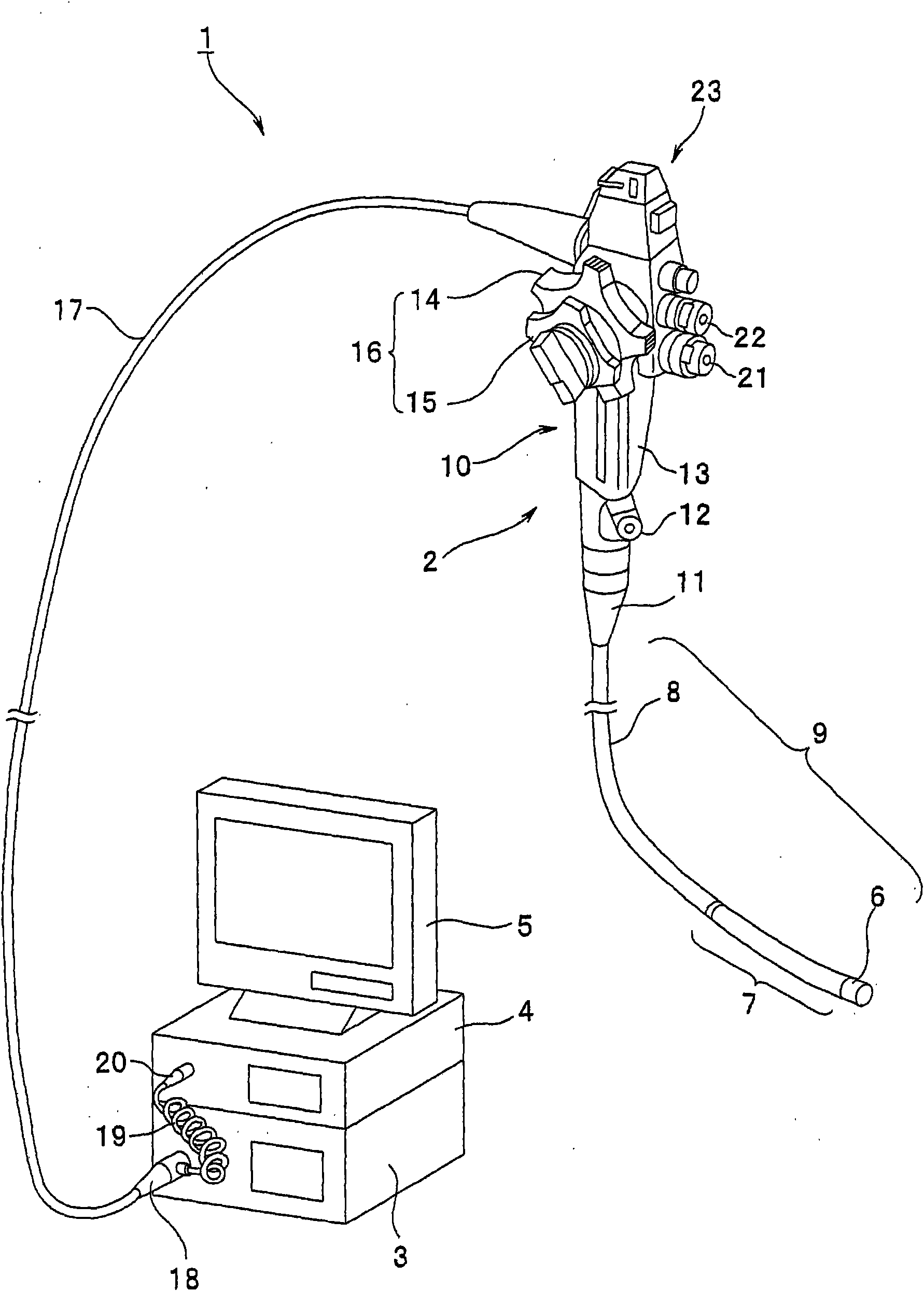
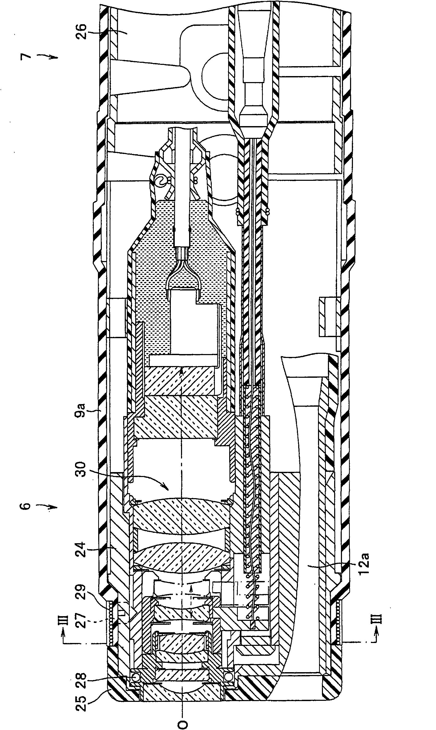
[0055] First, use Figure 1 to Figure 10 The present invention will be described. in addition, Figure 1 to Figure 10 Regarding the first embodiment of the present invention, figure 1 is a block diagram showing the entire electronic endoscope system, figure 2 is a cross-sectional view showing the internal structure of the distal end portion of the endoscope, image 3 is along figure 2 Sectional view of line III-III, Figure 4 is a cross-sectional view showing the structure of the imaging unit, Figure 5 is along Figure 4 A cross-sectional view of the V-V line, Image 6 is a block diagram showing a resistive feedback circuit within a video processor for drive control of a shape memory alloy actuator, Figure 7 It is a cross-sectional view of the imaging unit in which the lens frame is moved to the initial state at the wide-angle end position, Figure 8 is a graph showing the temperature-deformation relationship of a shape memory alloy wire, Figure 9 It is a cross-...
no. 2 approach
[0130] Next, a second embodiment of the present invention will be described below based on FIGS. 11 to 14 (A, B).
[0131] 11 to 14 (A, B) relate to the second embodiment of the present invention. FIG. 11 is a cross-sectional view showing the structure of the imaging unit, and FIG. The sectional view of the camera unit, Figure 13 (A, B) is a sectional view of the camera unit used to explain the effect of the moving lens frame moving to the telephoto end position, Figure 14 (A, B) is a sectional view showing the moving lens frame moving to the telephoto end position Cross-sectional view of the imaging unit in the state of the end position.
[0132] In the following description, the same reference numerals are used for the same configurations as those of the imaging unit 30 of the endoscope system 1 of the first embodiment described above, and detailed descriptions of these configurations are omitted.
[0133] However, in conventional endoscopes that change optical characterist...
no. 3 approach
[0161] Next, a third embodiment of the present invention will be described below based on FIGS. 15(A, B) to 18(A, B).
[0162] Fig. 15 (A, B) ~ Fig. 18 (A, B) relate to the third embodiment of the present invention, Fig. 15 (A, B) is the sectional view showing the structure of the imaging unit, Fig. 17(A, B) is a cross-sectional view of the imaging unit for explaining the effect of moving the moving lens frame to the telephoto end position. Figs. 18 (A, B) is a cross-sectional view showing a state in which a current is applied to the SMA wire again in the state where the moving lens frame has moved to the telephoto end position.
[0163] In the following description, the same reference numerals are used for the same configurations as those of the imaging unit 30 of the endoscope system 1 according to the first and second embodiments described above, and detailed descriptions of these configurations are omitted. In addition, the configuration of the imaging unit of this embodi...
PUM
 Abstract
Description
Claims
Application Information