
Control system for vehicle receiving power intermittently

A technology for control devices and power storage devices, applied in control devices, battery/fuel cell control devices, electric vehicles, etc., capable of solving maximum charge and discharge current limitations, lack of storage energy management methods, charge and discharge capacity limitations, charge and discharge current limitations , Don't like overcharging, overdischarging and other problems

Active Publication Date: 2009-12-09
HITACHI LTD
View PDF3 Cites 16 Cited by
  • Summary
  • Abstract
  • Description
  • Claims
  • Application Information

AI Technical Summary

Problems solved by technology

Furthermore, most power storage devices do not like overcharging and overdischarging, and in most cases there is a limit on the maximum charging and discharging current
Therefore, when using an energy storage device, it is indispensable to establish methods for managing stored energy, limiting charge and discharge capacity, and limiting charge and discharge current.

Method used


Image

  • Control system for vehicle receiving power intermittently
  • Control system for vehicle receiving power intermittently
  • Control system for vehicle receiving power intermittently

Examples


Embodiment 1

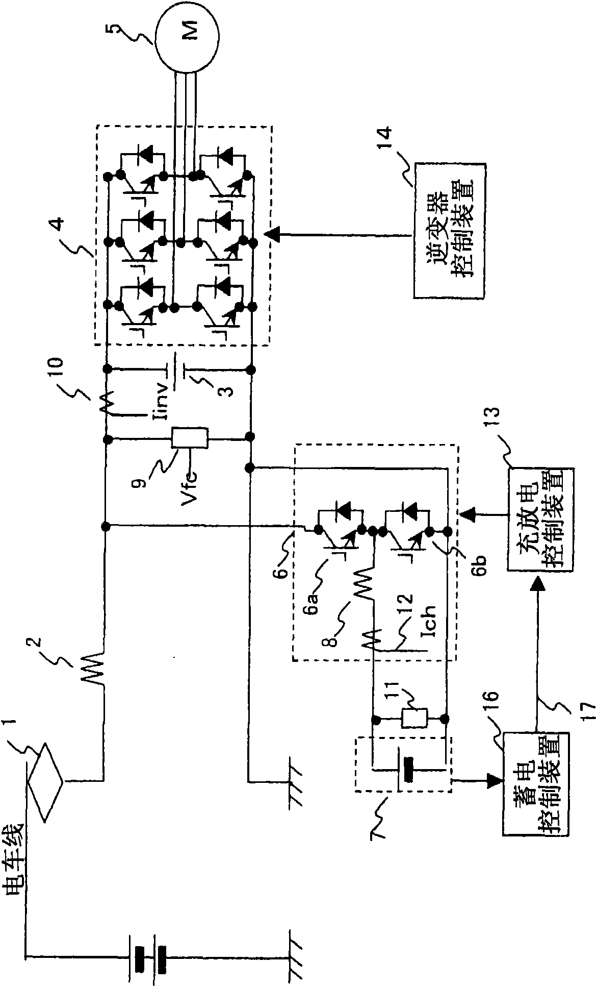
[0060] First, use figure 1 The structure of one embodiment of the present invention will be described. As shown in the figure, it includes a power collector 1 electrically connected to the electric train line and an inverter device 4 connected to the electric train line through a filter reactor 2. A filter capacitor 3 is connected to the input side of the inverter device 4. The main motor 5 is connected to the output side of the inverter device 4 .

[0061] Furthermore, a circuit breaker device 6 as a semiconductor switching device is connected in parallel to the smoothing capacitor 3 . This breaker device 6 is constituted by connecting the emitter of the first IGBT 6 a connected in parallel to the freewheel diode and the collector of the second IGBT 6 b connected in parallel to the freewheel diode. The collector of IGBT 6 a is connected between filter reactor 2 and inverter device 4 , and the emitter of IGBT 6 b is connected to the DC low potential side of inverter device 4...

Embodiment 2

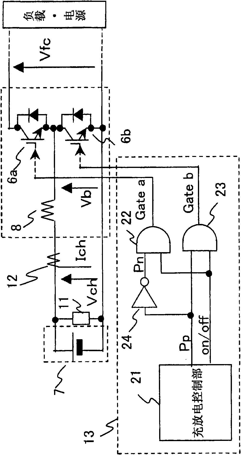
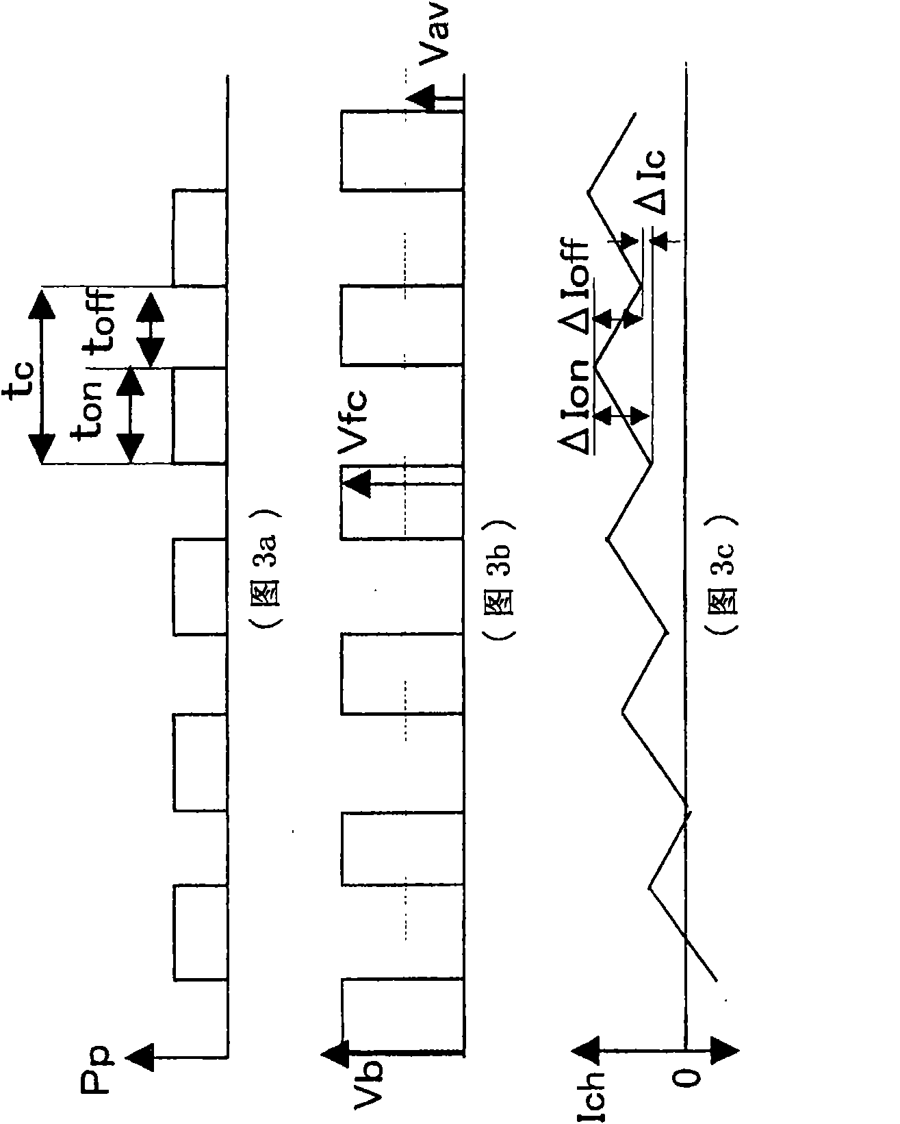
[0109] Next, another example of the charge and discharge control unit 21 will be shown. Figure 10 yes means figure 2 A block diagram of another configuration example of the charge-discharge control unit 21 shown. Figure 11 is used for Figure 10 A characteristic diagram of the SOC upper limit pattern generator 48, 48a of the structure shown. Figure 12 is said to be carried out by Figure 10 A graph of the voltage-current control characteristics during control of the structure shown.

[0110] The present embodiment is an effective embodiment when the electric storage device 7 has a large electric storage capacity and there is a surplus in the electric storage capacity required for traveling in the non-tramway section. Figure 4 The purpose of the embodiment is to travel reliably in the non-tram line section, so it is the highest priority to ensure that the storage capacity can reliably travel in the non-tram line section, also as Figure 8 As shown, when entering the t...


PUM


Abstract

A means for controlling a vehicle (e.g. a railway locomotive) driven by energy received intermittently from a source such as a catenary or third rail comprises a power storage system 7, an inverter 4 and a semiconductor switch 6. A DC voltage detecting means 9 measures the DC-side voltage of the inverter to determine whether the intermittent source is connected or not, and the charging or discharging of the power storage system through the inverter is controlled accordingly using the semiconductor switch. In this way the input voltage of the inverter is maintained within a predetermined operable range. A secondary battery DC voltage detector 11 may be provided to determine the terminal voltage of the power storage system. A charge / discharge control unit 13, inverter control unit 14, power storage control unit 16 and information transmission 17 means may also be provided.

Description

technical field [0001] The present invention relates to a control device mounted on a vehicle such as a railway vehicle, and more particularly to a vehicle control device having a power storage device provided on an input side of an inverter device for driving a main motor. Background technique [0002] In the prior art, it is the premise that electric power is obtained through the tram line to drive the vehicle in the electrified railway system. Equipped with section stop, subsequent movement cannot be performed. At such a point, the vehicle secures a predetermined speed in advance, and travels in the section where electric power cannot be supplied in that section by driving operations such as coasting through the section without a trolley line. [0003] Patent Document 1: JP-A-2005-328618 [0004] However, when such a train line non-equipped section is over a long distance, or there are sections with multiple frequencies, and there are restrictions on the driving method ...

Claims


Application Information

Patent Timeline
Patent Type & Authority Applications(China)
IPC IPC(8): B60L11/00B60L11/18
CPCB60L11/005B60L2200/26Y02T10/7022Y02T10/7005B60L11/1801B60L7/14B60L9/22B60L2240/529B60L2240/547B60L2240/549B60L2240/527B60M1/36B60L50/53B60L50/40B60L58/14B60L58/15Y02T10/70B60L5/04B60L5/18B60L5/39B60L9/18
Inventor 丰田瑛一大石亨一岛田基巳
Owner HITACHI LTD
Learn More