Control system for vehicle receiving power intermittently
A control device and power storage device technology, applied in control devices, battery/fuel cell control devices, electric vehicles, etc., can solve the problems of overcharging, overdischarging, maximum charging and discharging current limitation, lack of storage energy management methods, Charge and discharge capacity limitation, charge and discharge current limitation, etc.
- Summary
- Abstract
- Description
- Claims
- Application Information
AI Technical Summary
Problems solved by technology
Method used
Image
Examples
Embodiment 1
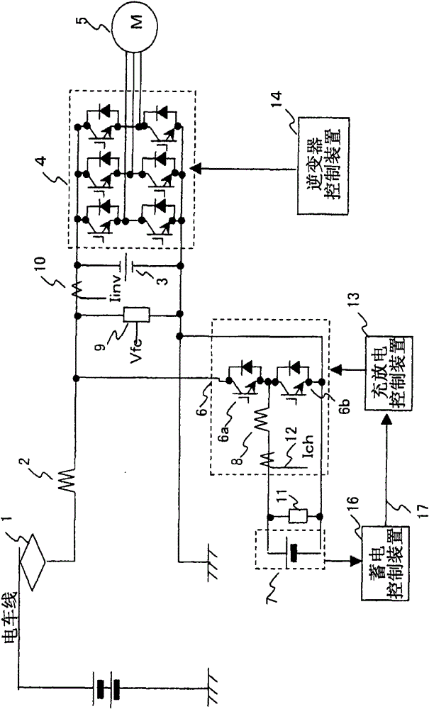
[0060] First, use figure 1 The structure of one embodiment of the present invention will be described. As shown in the figure, it includes a power collector 1 electrically connected to the electric train line and an inverter device 4 connected to the electric train line through a filter reactor 2. A filter capacitor 3 is connected to the input side of the inverter device 4. The main motor 5 is connected to the output side of the inverter device 4 .
[0061] Furthermore, a circuit breaker device 6 as a semiconductor switching device is connected in parallel to the smoothing capacitor 3 . This breaker device 6 is constituted by connecting the emitter of the first IGBT 6 a connected in parallel to the freewheel diode and the collector of the second IGBT 6 b connected in parallel to the freewheel diode. The collector of IGBT 6 a is connected between filter reactor 2 and inverter device 4 , and the emitter of IGBT 6 b is connected to the DC low potential side of inverter device 4...
Embodiment 2
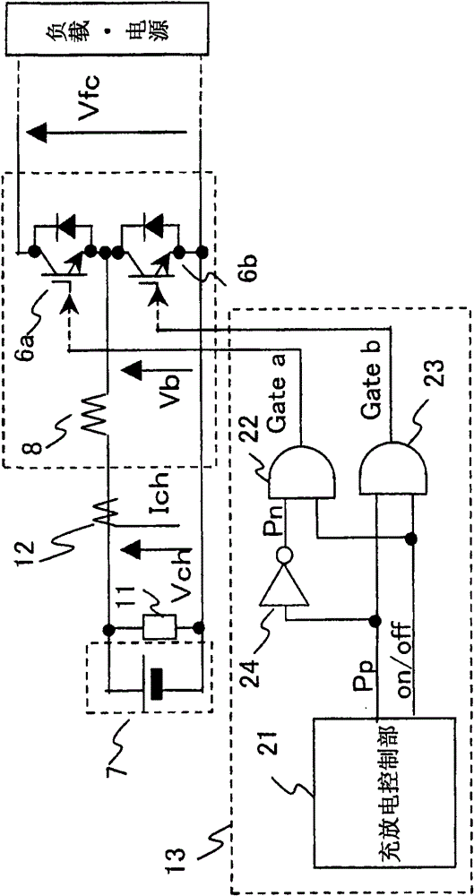
[0109] Next, another example of the charge and discharge control unit 21 will be shown. Figure 10 yes means figure 2 A block diagram of another configuration example of the charge-discharge control unit 21 shown. Figure 11 is used for Figure 10 A characteristic diagram of the SOC upper limit pattern generator 48, 48a of the structure shown. Figure 12 is said to be carried out by Figure 10 A graph of the voltage-current control characteristics during control of the structure shown.
[0110] The present embodiment is an effective embodiment when the electric storage device 7 has a large electric storage capacity and there is a surplus in the electric storage capacity required for traveling in the non-tramway section. Figure 4 The purpose of the embodiment is to travel reliably in the non-tram line section, so it is the highest priority to ensure that the storage capacity can reliably travel in the non-tram line section, also as Figure 8 As shown, when entering the t...
PUM
 Abstract
Description
Claims
Application Information
 - R&D
- Intellectual Property
- Life Sciences
- Materials
- Tech Scout
- Unparalleled Data Quality
- Higher Quality Content
- 60% Fewer Hallucinations
Browse by: Latest US Patents, China's latest patents, Technical Efficacy Thesaurus, Application Domain, Technology Topic, Popular Technical Reports.
© 2025 PatSnap. All rights reserved.Legal|Privacy policy|Modern Slavery Act Transparency Statement|Sitemap|About US| Contact US: help@patsnap.com


