Milling mechanism and cutter thereof

A mechanical and milling technology, which is applied in roads, constructions, road repairs, etc., can solve the problems of low cost of use, achieve the effects of prolonging the service life, increasing the rotation performance, and solving the problem of eccentric wear

Inactive Publication Date: 2009-12-09
SANY HEAVY IND CO LTD (CN)
View PDF0 Cites 12 Cited by
  • Summary
  • Abstract
  • Description
  • Claims
  • Application Information

AI Technical Summary

Problems solved by technology

[0011] The technical problem to be solved by the present invention is to provide a cutting tool for milling machinery, which can effectively solve the problem of eccentric wear of the cutting tool in the construction process, thereby prolonging the service life of the cutting tool; Milling machinery for knives, which is less expensive to use during construction

Method used


Image

  • Milling mechanism and cutter thereof
  • Milling mechanism and cutter thereof
  • Milling mechanism and cutter thereof

Examples


Embodiment Construction

[0029] The core of the present invention is to provide a milling machine tool, which can effectively solve the problem of eccentric wear of the tool in the working process, thereby prolonging the service life of the tool.

[0030] In order to enable those skilled in the art to better understand the technical solutions of the present invention, the present invention will be further described in detail below in conjunction with the accompanying drawings and specific embodiments.

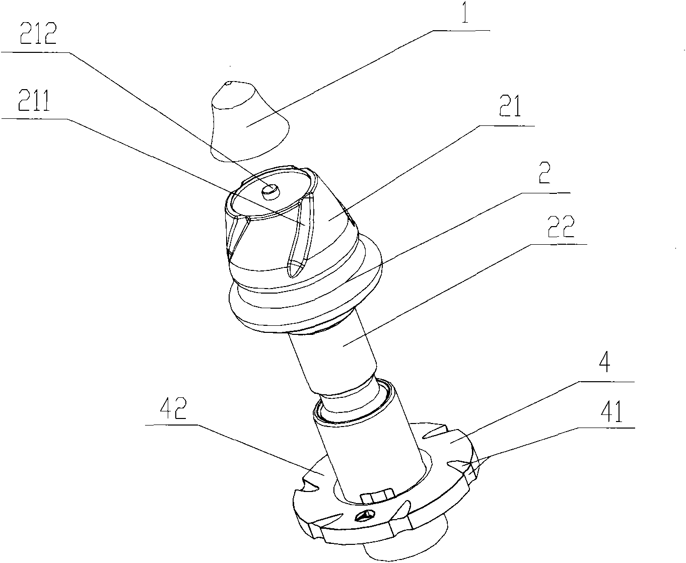
[0031] Please refer to figure 2 , figure 2 It is an isometric view of the separation of the cutter head and the cutter body of the cutter of the milling machine in a specific embodiment of the present invention.

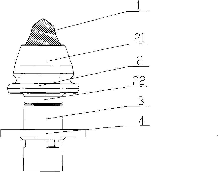
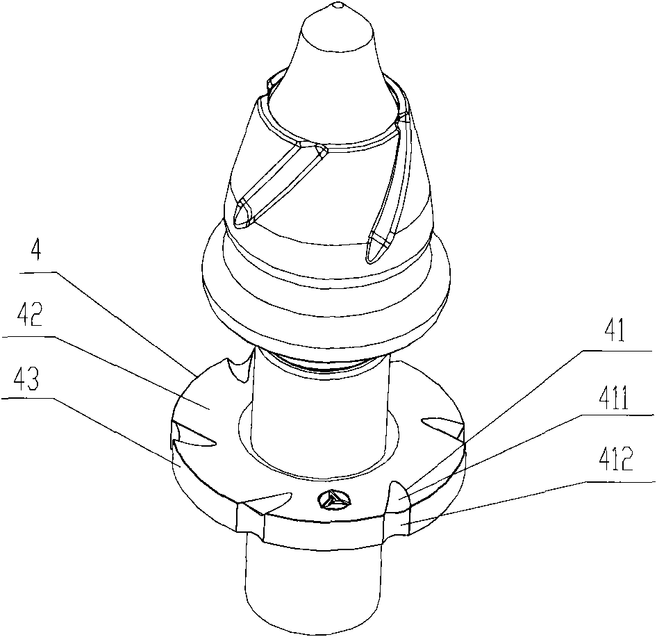
[0032] In the first embodiment, if figure 2 As shown, the present invention provides a milling machine tool, including a cutter head 1, a cutter body 2, and an annular spacer 4; the cutter body 2 includes a frustum-shaped head 21 and a cylindrical body 22, and the cutter head 1 is connec...


PUM


Abstract

The invention discloses a cutter of a milling mechanism, which comprises a cutter head, a cutter body and an annular gasket, wherein the cutter body comprises a round platform shaped head and a cylindrical body, the cutter head is connected with the round platform shaped head, and the annular gasket is sleeved on the cylindrical body; and the lateral wall of the round platform shaped head is provided with a first groove which intersects with the generating line of a rotating surface and forms proper included angle, the annular gasket is provided with a channel generally extending along the circumferential direction, and the channel is communicated with the upper surface and the lower surface of the annular gasket. By adopting the cutter of the milling mechanism, the problem of eccentric wear of the cutter is effectively solved so that the service life of the cutter is prolonged.

Description

technical field [0001] The invention relates to the technical field of machinery, in particular to a milling machine. The invention also relates to a cutter for a milling machine. Background technique [0002] Milling machine is usually a kind of maintenance machine used to remove pavement materials. The milling rotor rotating at high speed and covered with knives cuts concrete pavement such as asphalt and cement by down milling or up milling. Due to the complex composition and high hardness of the pavement material, the severe wear of the tool makes it a relatively fast-consuming component, which significantly increases the construction cost. [0003] The main working part of the milling machine is the milling rotor. The milling rotor is composed of the milling rotor shaft and a plurality of cutters. The cutters include the cutter body and the cutter head. [0004] Please refer to figure 1 , figure 1 It is a structural schematic diagram of a typical milling machine tool...

Claims


Application Information

Patent Timeline
Patent Type & Authority Applications(China)
IPC IPC(8): E01C23/088
Inventor 王世旺赵明辉
Owner SANY HEAVY IND CO LTD (CN)
Why Eureka
Try Eureka