
Large lattice structure with plate type grid substructure and cylindrical surface type crossed space truss system

A three-dimensional truss and grid structure technology, which is applied to building components, building structures, roofs, etc., can solve the problems of small structural thickness-span ratio, complex processing structure, and increased steel consumption, so as to reduce the workload of on-site installation , Save steel consumption and reduce project cost

Inactive Publication Date: 2009-12-09
HUNAN UNIV
View PDF0 Cites 13 Cited by
  • Summary
  • Abstract
  • Description
  • Claims
  • Application Information

AI Technical Summary

Problems solved by technology

The double-layer cylindrical reticulated shell structure is a structural form widely used in large-span space structures at present, and this kind of double-layer cylindrical reticulated shell structure will have some inevitable problems with the further increase of the span, such as using 5m When the rods are within the usual length, the structure will easily lead to overall instability due to the small thickness-span ratio; and when the rods are too long, the pressure rods will easily become unstable due to excessive internal force, and the resulting steel Volume increase, etc.
Some literature analysis shows that the effect of increasing the number of layers on improving the overall performance of the structure is not obvious. What is more important is that it is not feasible to increase the span of the structure by using multi-layer forms to break through the limitation of internal forces. , the node makes the processing structure more complex due to too many connected rods

Method used


Image

  • Large lattice structure with plate type grid substructure and cylindrical surface type crossed space truss system
  • Large lattice structure with plate type grid substructure and cylindrical surface type crossed space truss system
  • Large lattice structure with plate type grid substructure and cylindrical surface type crossed space truss system

Examples


Embodiment 1

[0020] combine figure 1 with figure 2 :

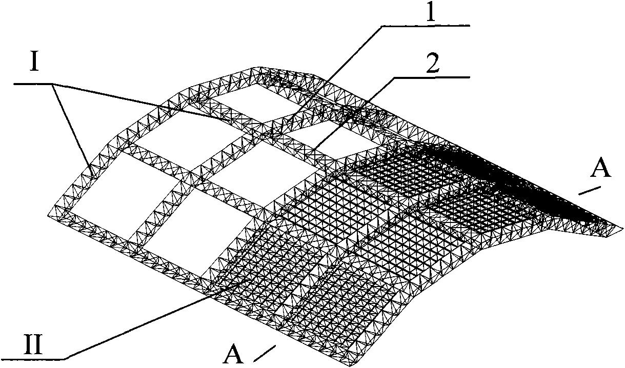
[0021] The whole structure is composed of main structure I and substructure II arranged in the main structure. The main structure I is a large cylindrical grid structure formed by the intersection of horizontal three-dimensional truss 1 and vertical three-dimensional truss 2. The grid size is 10-30m. The substructure is an ordinary double-layer flat grid frame, which is embedded in the large grid to form a structural form of a large grid with a small grid. The load of the entire structure is relatively sparse. And the grand main structure bears.

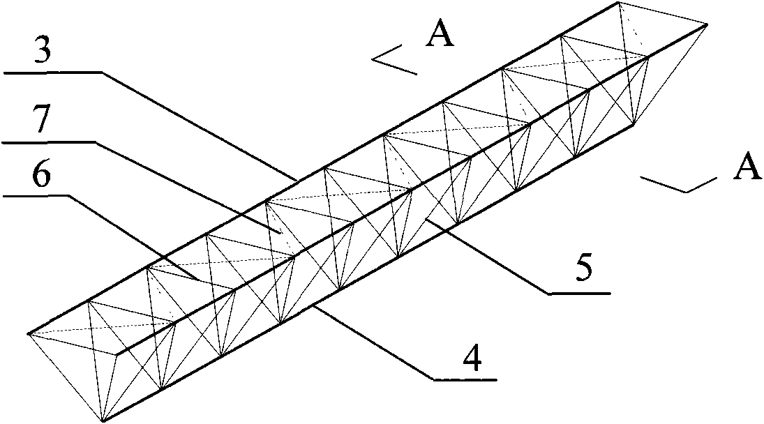
[0022] combine image 3 with Figure 4 : The horizontal three-dimensional truss 1 and the vertical three-dimensional truss 2 are all composed of two parallel upper chords 3 and one lower chord 4 to form a triangular section, a web 5 is arranged between the upper chord and the lower chord, and a web 5 is arranged between the two upper chords A plurality of crossbars 6, the distance betwe...

Embodiment 2

[0026] combine Figure 8 with Figure 9 : The difference between this embodiment and Embodiment 1 is that: the substructure II of this embodiment is embedded in the large grid of the main structure I in the manner of support at multiple points 11 around.


PUM


Abstract

The invention discloses a large lattice structure with plate type grid substructure and cylindrical surface type crossed space truss system, comprising a main structure and a substructure in the main structure. The main structure is a cylindrical surface type large lattice structure composed of crossed horizontal and vertical space trusses with size of 10 to 30m. The substructure is ordinary double-layered plate type grid and internally embedded in the large lattice in the four-corner point support or surrounding multi-point support way to form a structure with smaller lattice embedded in the larger lattice. The invention can effectively conquer the problem of strut buckling, improve the global stiffness and stability of the structure at a large amount, save steel and reduce construction cost. The large lattice structure can be processed in the factory and then transported to the field to assemble so as to greatly reduce the field installing work and shorten the construction time and fit for super large span spatial latticed structure of 150 to 200m.

Description

technical field [0001] The invention relates to the field of space structures in the construction industry, in particular to a flat net frame structure, cylindrical surface crossing three-dimensional truss system giant grid structure suitable for super-large-span roofs. Background technique [0002] With the development of society, the large-span spatial structure is bound to develop into super-long-span. The double-layer cylindrical reticulated shell structure is a structural form widely used in large-span space structures at present, and this kind of double-layer cylindrical reticulated shell structure will have some inevitable problems with the further increase of the span, such as using 5m When the rods are within the usual length, the structure will easily lead to overall instability due to the small thickness-span ratio; and when the rods are too long, the pressure rods will easily become unstable due to excessive internal force, and the resulting steel volume increas...

Claims


Application Information

Patent Timeline
Patent Type & Authority Applications(China)
IPC IPC(8): E04B7/10E04B1/342
Inventor 贺拥军周绪红
Owner HUNAN UNIV
Learn More