Steel rail flash welding machine

A flash welding machine and rail technology, applied in welding equipment, resistance welding equipment, metal processing equipment, etc., can solve the problems of complex structure, large size and weight, and difficult manufacturing.

Active Publication Date: 2009-12-16
CHANGZHOU RUITAI ENG MASCH CO LTD +1
View PDF1 Cites 20 Cited by
  • Summary
  • Abstract
  • Description
  • Claims
  • Application Information

AI Technical Summary

Problems solved by technology

Among them, although the hydraulic multiplier installed in the piston rod of the clamping cylinder can increase the force, its control valve is installed on the connecting piece at the end of the piston rod, which has a complicated structure and is difficult to manufacture and maintain; The structure is more complicated, the size and weight are large, the manufacture is difficult, and there is a risk of oil leakage in the guide part
In addition, it cannot control the output clamping force, which is not convenient for construction operation

Method used


Image

  • Steel rail flash welding machine
  • Steel rail flash welding machine
  • Steel rail flash welding machine

Examples


Embodiment Construction

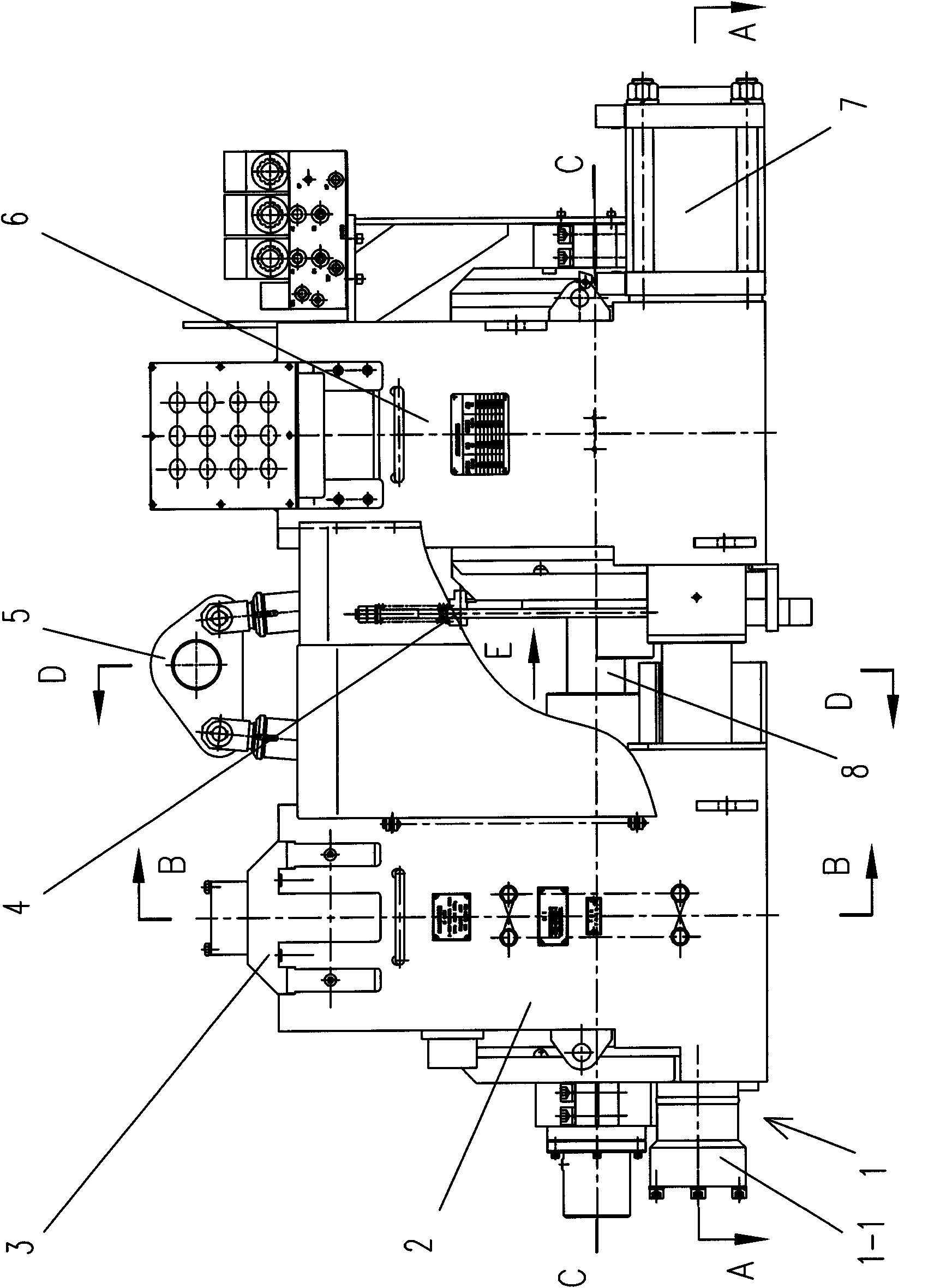
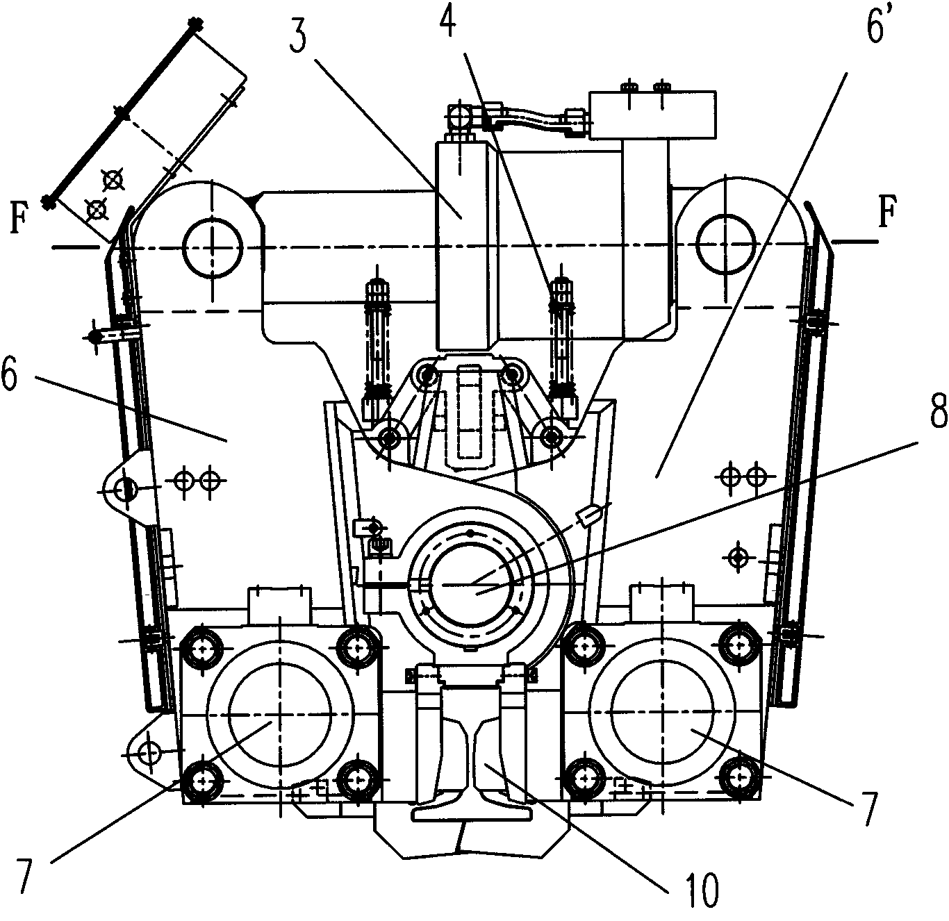
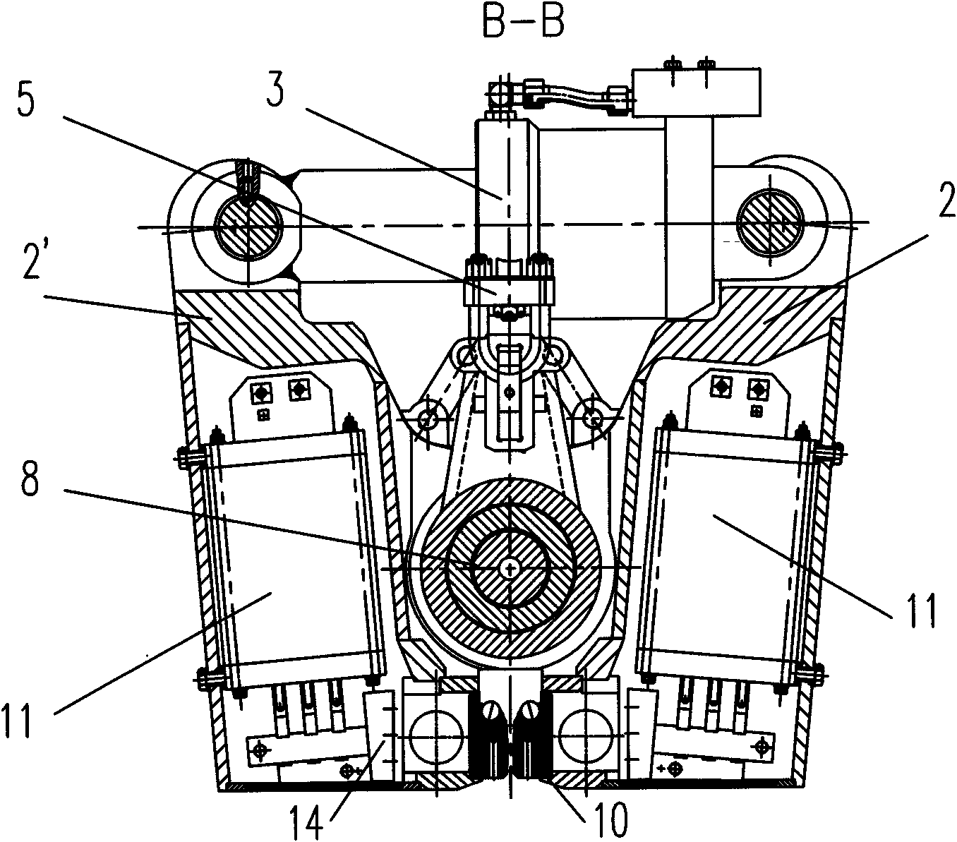
[0043] Such as figure 1 , 2 , 3, 4, 5, 6, 7, 8, and 9, the rail flash welding machine of the present invention includes a first pair of boxes 2, 2', a second pair of boxes 6, 6', a central axis 8, Clamping cylinder 3, upsetting cylinder 7, tumor pushing device 1 and welding transformer 11, wherein the first pair of boxes 2, 2' and the second pair of boxes 6, 6' are mounted on a common central axis 8 through hinges Two pairs of pincer clamping devices, each pair of pincer clamping devices is equipped with a clamping cylinder 3 between the boxes to drive the first pair of boxes 2, 2' and the second pair of boxes 6, 6' around the center The shaft 8 rotates axially, and an upsetting oil cylinder 7 is installed between the first pair of boxes 2, 2' and the second pair of boxes 6, 6' to realize the relative movement of the two pairs of boxes along the axis of the central axis 8, and the two welding The transformer 11 is installed in the first pair of boxes 2, 2' or the second pair...


PUM


Abstract

The invention discloses a steel rail flash welding machine, which comprises a first pair of box body, a second pair of box body, a central shaft, a clamping oil cylinder, an upsetting oil cylinder, a knob removing device and a welding transformer, wherein the clamping oil cylinder comprises a cylinder body, a piston, a piston rod, a piston rod end connecting piece and an end cover; the cylinder body is divided into a first cavity and a second cavity; the inside of the piston rod is provided with a supercharged piston; the inner cavity of the piston rod is divided into a third cavity and a fourth cavity; the end part of the cylinder body is provided with a first oil line and a second oil line and is connected with a hydraulic integrated block provided with an electromagnetic reversing valve, a pilot reducing valve and a hydraulic control one-way valve; and the periphery of an oil conduit at least forms a segment of sliding fit with the through hole of the supercharged piston. The steel rail flash welding machine is large in clamping force, simple and reasonable in structure, facilitates the control of the output clamping force and is suitable for welding steel rails with different lengths and weights.

Description

technical field [0001] The invention relates to flash butt welding equipment, in particular to a rail flash welding machine. Background technique [0002] At present, the existing domestic rail flash welding machines can only weld long rails below 100 meters due to insufficient clamping force, which cannot meet the needs of welding 500 meters or longer long rails and lock welding. Chinese patent application number 98106266.0 discloses a flash butt welding rail welding machine, which includes two double-armed pincer clamping devices and is assembled on a common mandrel, the two are insulated from each other and can The two upsetting hydraulic cylinders connected to them move relatively along the above-mentioned mandrel, and one end of each double arm is hinged on the piston rod of the clamping hydraulic cylinder, and the other end is equipped with clamping long claws and conductive claws; The two welding transformers are installed in the hollow double-arm rod of one of the t...

Claims


Application Information

Patent Timeline
Patent Type & Authority Applications(China)
IPC IPC(8): B23K11/04
Inventor 王有虹夏青顺黄腾飞宋自帅梁灰曹志国刘晓磊郦雪云
Owner CHANGZHOU RUITAI ENG MASCH CO LTD
Why Eureka
Try Eureka