Non-contact tension detection and feedback control mesh belt winding device

A technology of tension detection and feedback control, applied in the direction of non-electric variable control, mechanical pressure/force control, electromechanical devices, etc., can solve the problems of easily changing the tension of the webbing, affecting the accuracy of the detection results, and the adjustment effect is not real-time and fast enough to achieve Accurate detection results, rapid and more effective tension adjustment

Inactive Publication Date: 2009-12-16
珠海蓝坊智能设备有限公司
1 Cites 36 Cited by

AI-Extracted Technical Summary

Problems solved by technology

[0005] (1) The radius detector and tension sensor used are contact detection, that is, contact with the webbing or the package to obtain the detection signal. This contact detection is easy to change the tension of the webbing itself and affect th...

Abstract

The invention relates to textile equipment, particularly relates to a non-contact tension detection and feedback control mesh belt winding device, comprising a winding roller which drives the mesh belt to convolute to weave and is driven by an AC asynchronous motor; a charge couple device image sensor is arranged outside the mesh belt between two guide rollers, an ultrasonic wave sensor is arranged on the periphery of a ball of mesh belts, the charge couple device image sensor is connected with an image acquisition card, the ultrasonic wave sensor is connected with a signal acquisition card and the image acquisition card, the signal acquisition card is connected with a PC industrial personal computer connected with a motion control card, and the motion control card is connected with the AC asynchronous motor by a frequency converter; and a tension regulating device is arranged adjacently to the winding roller. The invention carries out non-contact detection on the variation of the tension force and the winding radius of the mesh belt and can not influence the tension force of the mesh belt due to the contact of the mesh belt, and the detection result is more accurate; and the tension force of the mesh belt is regulated by combining the operation of regulating the speed of the motor with the operation of driving a regulating roller by an air cylinder, thus the regulation of the tension force is faster and more effective.

Application Domain

Auxillary apparatusMechanical energy handling +3

Technology Topic

Image

  • Non-contact tension detection and feedback control mesh belt winding device
  • Non-contact tension detection and feedback control mesh belt winding device
  • Non-contact tension detection and feedback control mesh belt winding device

Examples

  • Experimental program(1)

Example Embodiment

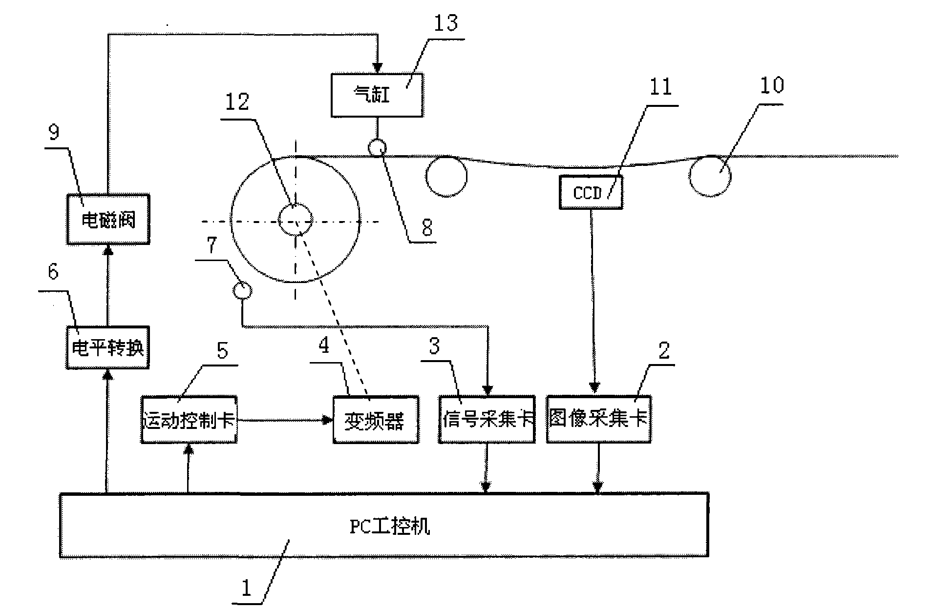
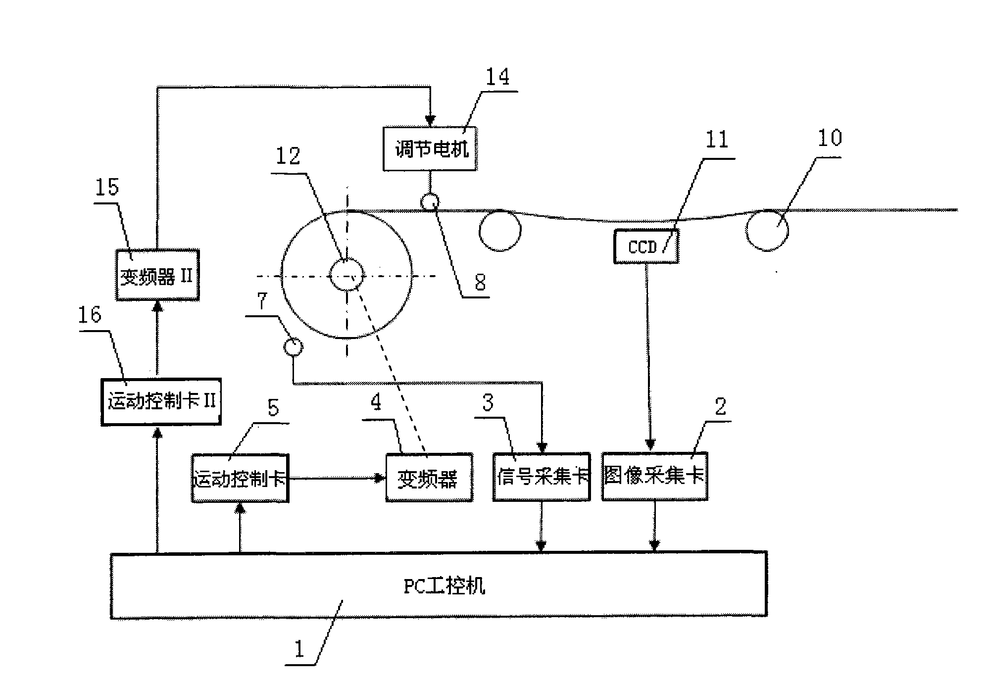
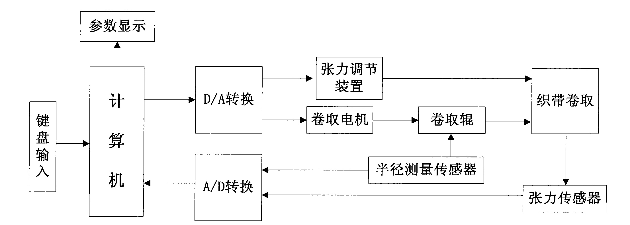
[0019] In order to better understand the present invention, the technical solutions of the present invention will be further described below in conjunction with the accompanying drawings and embodiments, see Figure 1 to Figure 4 :
[0020] The webbing winding device with non-contact tension detection and feedback control implemented according to the present invention includes a winding roller, which is driven to rotate by a winding motor 12 to wind the webbing around the roller. The winding motor 12 adopts AC Asynchronous motor. The linear velocity of the webbing is equal to the product of the angular velocity and the radius of the package, and as the winding progresses, the radius of the package increases. If the speed of the winding motor 12 remains unchanged, the linear velocity of the webbing will increase , Causing the webbing tension to increase. When the tension range of the webbing exceeds 10% of the initial tension, it will have a significant impact on the weaving effect, so the radius of the package and the tension of the webbing must be tested. The determination of the initial tension of the webbing is affected by many factors such as the diameter of the take-up roll and the type of webbing. The tension of the webbing is proportional to the webbing linear speed. If the webbing linear speed is 0.01 m/min, the webbing tension is better when the webbing is wound, so the initial webbing The tension is determined by measuring with a hand-held electronic tension measuring instrument when the webbing linear speed is 0.01 m/min and the package radius is the radius of the take-up roll. The median value is taken five times to reduce the error.
[0021] The present invention adopts the following scheme: a charge coupling device image sensor 11 is arranged on the outside of the webbing between the two guide rollers 10, an ultrasonic sensor 7 is arranged on the outer circumference of the package, and the charge coupling device image sensor 11 and the ultrasonic sensor 7 are both non-contact detection sensor.
[0022] The charge coupling device image sensor 11 is connected to the image capture card 2, and the image capture card 2 is connected to the PC industrial computer 1. The charge coupling device image sensor 11, that is, the CCD sensor is made of high-sensitivity semiconductor materials, which can convert light The charge is converted into a digital signal by the analog-to-digital converter chip. The CCD image sensor 11 has the advantages of high accuracy, high sensitivity, self-scanning, and wide spectral response, and is therefore widely used in image scanning, non-contact size detection, and the like.
[0023] The CCD sensor 11 used in this embodiment is a VISION MV-1300FC/FM industrial camera, which has the characteristics of high resolution and good image quality, and is used in industrial inspection, intelligent transportation, machine vision, scientific research, military science, aerospace, etc. In many fields, compared with CMOS digital cameras, no matter it is static or dynamic collection, high-quality images without distortion can be obtained. The camera of this model has a resolution of 1280×1024 pixels, and the acquisition frame rate is 14 frames per second. The image acquisition card 2 uses the Vision MV-M2000 image acquisition card 2. The card has a maximum point frequency of 220M and an acquisition resolution of 1280×1024. . Insert the Vision MV-M2000 image acquisition card 2 directly into the expansion slot of the main board of the PC industrial computer 1, and transfer data through the PCI data bus. The signal line that comes with the Vision MV-1300FC/FM industrial camera is connected to the video input jack of the image card, and the Vision MV-1300FC/FM industrial camera comes with a stand, which is set on the outside of the webbing between the two guide rollers 10. The static image of the webbing between the guide rollers 10 is captured and converted into a video signal and sent to the image card. The image card collects the video signal in real time and performs A/D conversion and then stores it in the storage channel for the PC industrial computer 1 to call and process. The collection interval is 0.01s.
[0024] During the webbing winding process, there is a functional relationship between the webbing tension and the geometrical parameters of the webbing shape. If the sag angle of the webbing is measured, the webbing tension can be calculated. The specific calculation formula is: F = ρLg cos α , In the formula, F-webbing tension (N), ρ-webbing linear density (Kg/m), α-webbing and vertical direction included angle, g-gravity constant, L-webbing length between guide rollers. Since the angle α is very small, L takes the linear distance between the guide rollers. The initial tension value is recorded as F 0 , F 0 = ρLg cos α 0 , α 0 Is the initial angle, α is detected during the coiling process, when cosα/cosα 0 When it reaches 1.1, the real-time tension F of the webbing exceeds the initial tension F 0 Of 10%, the tension must be adjusted.
[0025] The ultrasonic sensor 7 includes an ultrasonic transmitter and an ultrasonic receiver. The ultrasonic sensor 7 is fixedly installed on the frame on the periphery of the package. The ultrasonic sensor 7 is connected to the signal acquisition card 3, and is connected to the PC industrial computer after the signal acquisition card A/D conversion. 1. Ultrasonic distance measurement adopts the reflection type distance measurement method based on sending and receiving pulses in the same place, recording the time interval t of ultrasonic wave from transmitting to receiving, and calculating the measured distance according to the formula S=Ct/2, where S-transmitter and The distance between the packages, the propagation speed of C-ultrasonic waves, since the speed of sound of ultrasonic waves at a temperature of 10°~30° is 338m/s and 349m/s, respectively, there is little change, so C takes the sound speed of 344m/s at a temperature of 20° , After measuring the distance between the transmitter and the package, calculate the radius of the package R=S 0 -S+R j , S 0 -The distance between the transmitter and the take-up roller surface measured at the beginning of coiling, R j -Take-up roll radius. S=S at the beginning of coiling 0 , R 0 =R j.
[0026] Since F=KωR, where K is the proportional constant between the webbing tension and the webbing linear velocity, ω is the angular velocity of the winding shaft, and R is the radius of the package. When ω remains unchanged, the ribbon tension F and R are in a positive proportional relationship. When the detected change in R exceeds 10%, the angular velocity ω of the winding motor 12 needs to be adjusted to keep the change in F within 10%.
[0027]The winding roller is driven by the winding motor 12, and the winding speed is adjusted by adjusting the speed of the winding motor 12, thereby adjusting the webbing tension. The winding motor 12 adopts an AC asynchronous motor, and the PC industrial computer 1 is connected with a motion control card 5. After the control card 5 completes the D/A conversion, it is connected to the AC asynchronous motor through the inverter 4, and the speed of the winding motor 12 can be adjusted by adjusting the frequency of the inverter 4, and the motion control card 5 performs A/D conversion and level conversion effect. And feedback control is performed through the tension signal collected by the CCD sensor 11, and when the tension change range is within 10% of the preset value, the adjustment of the motor speed is stopped. In order to adjust the tension more quickly and effectively, at the same time, a tension adjusting device is installed near the take-up roller. The tension adjusting device includes a power mechanism and an adjusting roller 8. The output end of the power mechanism is connected to the adjusting roller 8. The power mechanism is controlled by a PC industrial computer 1. control. There are two forms of power mechanism. The power mechanism in Example 1 uses cylinder 13, which is fixed in cylinder, the end of the piston rod is hinged with adjusting roller 8, cylinder 13 is equipped with solenoid valve 9, and PC industrial computer 1 undergoes level conversion. After the device 6 is connected to an electrical connection solenoid valve 9, the control solenoid valve 9 can control the cylinder 13 to reverse, start, and stop. The other structure of the second embodiment is the same as that of the first embodiment. The difference is that the power mechanism of the tension adjusting device includes the adjusting motor 14, the rack and pinion transmission device, and the adjusting roller 8. The gear is connected to the output shaft of the adjusting motor 14, and the end of the rack Articulated adjusting roller 8, gear rack meshing transmission. The adjusting motor 14 is an AC motor equipped with a frequency converter II 15, which is controlled and driven by the PC industrial computer 1 through the motion control card II 16. The tension adjustment device cooperates with the motor of the take-up roller to adjust the tension of the webbing. When the webbing tension is too large, the adjustment roller 8 moves upward to reduce the winding angle of the webbing to reduce the tension. On the contrary, the adjustment roller 8 moves downward to increase the tension. Large webbing angle to increase tension.
[0028] The implementation process of the present invention is: determine the initial tension of the webbing, use the keyboard to input the preset range of the webbing tension change value, that is, 10% of the initial value, start the winding motor 12, and the webbing winding starts, every interval between the CCD sensor 11 and the ultrasonic sensor 7 0.01s to detect the tension of the webbing and the package radius on the take-up roller. When it is detected that the package radius has increased beyond the range or the webbing tension exceeds the range, the speed of the take-up motor 12 is reduced, and the adjustment roller 8 is moved up and down. Position, the tension to be detected falls within the allowable range again, and the adjustment stops.
[0029] The above-disclosed are only preferred embodiments of the present invention. Of course, the scope of rights of the present invention cannot be limited by this. Therefore, equivalent changes made according to the scope of patent application of the present invention still belong to the protection scope of the present invention.

PUM

no PUM

Description & Claims & Application Information

We can also present the details of the Description, Claims and Application information to help users get a comprehensive understanding of the technical details of the patent, such as background art, summary of invention, brief description of drawings, description of embodiments, and other original content. On the other hand, users can also determine the specific scope of protection of the technology through the list of claims; as well as understand the changes in the life cycle of the technology with the presentation of the patent timeline. Login to view more.

Similar technology patents

Classification and recommendation of technical efficacy words

Why Eureka
Try Eureka