Position change device for polarizing sheet

A polarizer and polarization-maintaining technology, which is applied in nonlinear optics, instruments, optics, etc., can solve problems such as obstacles and shorten the time of assembly line work, and achieve the effect of miniaturization and simplified structure

Active Publication Date: 2009-12-16
YODOGAWA MEDEC
View PDF1 Cites 1 Cited by
  • Summary
  • Abstract
  • Description
  • Claims
  • Application Information

AI Technical Summary

Problems solved by technology

Stopping the transportation of liquid crystal cell substrates has become an important reason that hinders the further shortening of assembly time.

Method used


Image

  • Position change device for polarizing sheet
  • Position change device for polarizing sheet
  • Position change device for polarizing sheet

Examples


Embodiment Construction

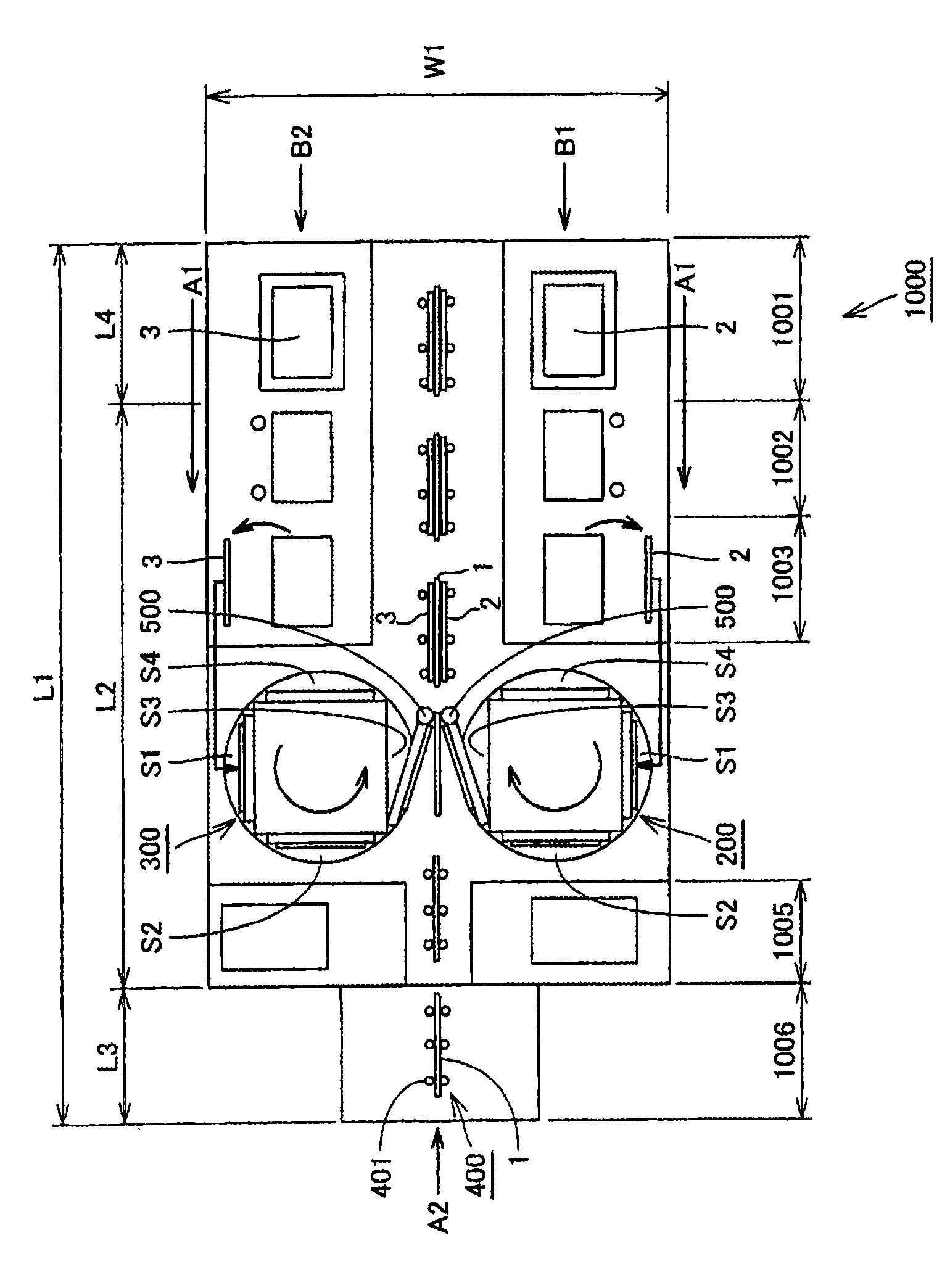
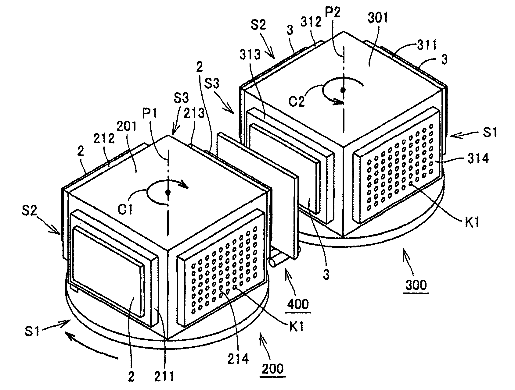
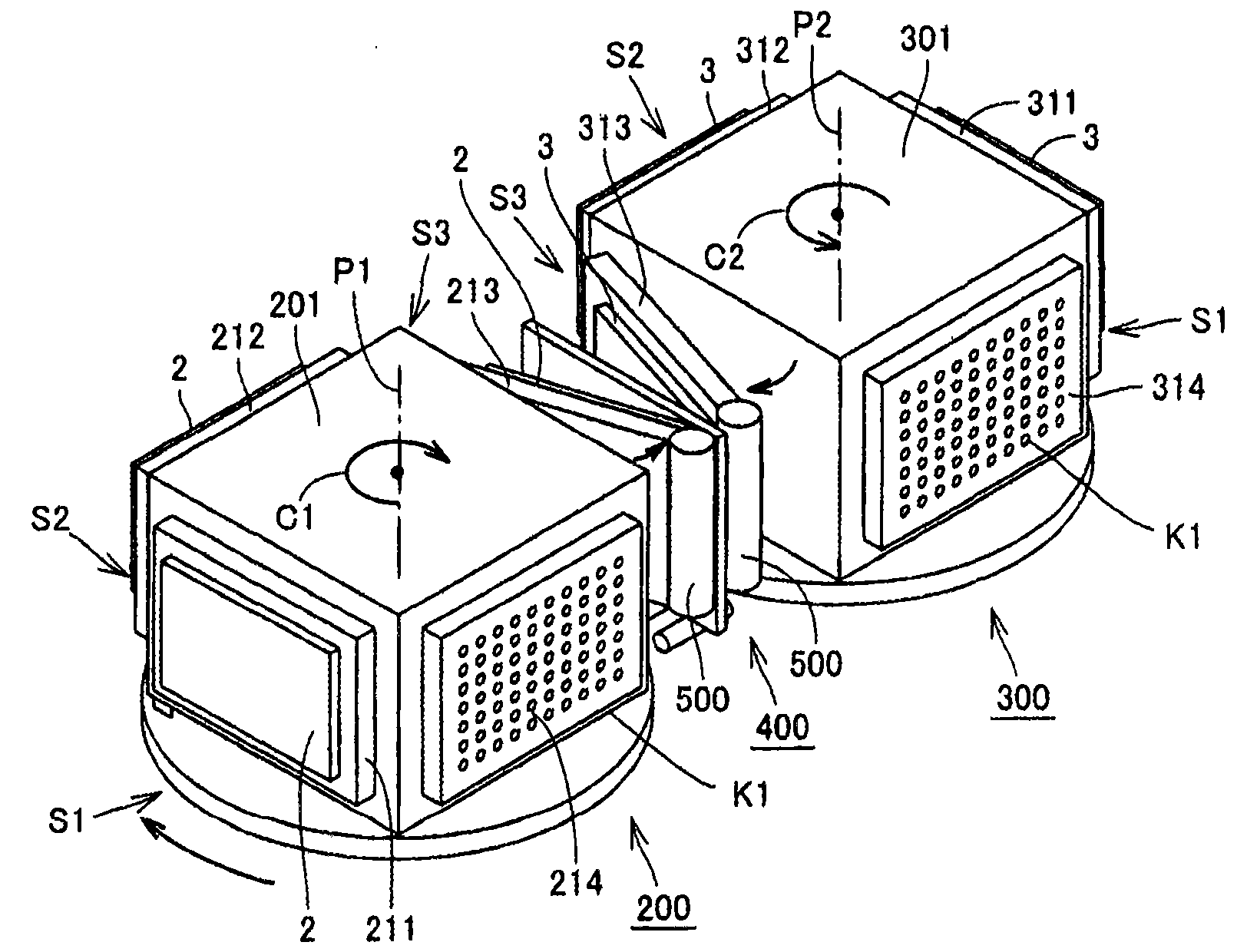
[0034] Next, a polarizer sticking device according to an embodiment of the present invention will be described with reference to the drawings. first, Figure 1 ~ Figure 3 The inventors of this application show a polarizing plate sticking device realized through the development process of the polarizing plate sticking device of the present invention based on the polarizing plate sticking device disclosed in the above-mentioned prior art document 1. figure 1 It is a plan view showing the overall configuration of the polarizer sticking device 1000, figure 2 It is a first perspective view showing the configuration of the first polarizing plate sticking device 200 and the second polarizing plate sticking device 300 employed in the polarizing plate sticking device 1000, image 3 It is a 2nd perspective view which shows the structure of the 1st polarizer sticking apparatus 200 and the 2nd polarizer sticking apparatus 300 used for the polarizer sticking apparatus 1000.

[0035]

...


PUM


Abstract

The invention relates to a polarizing sheet sticking device. A first polarizing sheet sticking device (600) and a second polarizing sheet sticking device (700) are provided with frame components (601 and 701) which are rotationally arranged by using rotating shafts (P11 and P12) as centers and are provided with four lateral surfaces. Therefore, when polarizing sheets (2 and 3) are stuck to a liquid crystal unit substrate (1) at a polarizing sheet sticking station (S14), covered films can be peeled from the polarizing sheets (2 and 3) at a covered film peeling station (S13), and the polarizing sheet (3) is accepted at a polarizing sheet accepting station (S11). As a result, the polarizing sheet sticking device which can inhibit the increment of the bottom area thereof due to large size of a color liquid crystal display can be provided.

Description

[0001] This application is a divisional application of the previous application (application date: September 8, 2006, application number: 200680008308.4, invention name: polarizer sticking device). technical field [0002] The present invention relates to a polarizer sticking device, and relates to a structure of a polarizing plate sticking device capable of suppressing an increase in the bottom area of ​​the device even when liquid crystal cell substrates are increased in size. Background technique [0003] In recent years, color liquid crystal displays are developing toward larger sizes. The mainstream size of color liquid crystal displays has reached 32 inches to 46 inches, and the size of color liquid crystal displays will accelerate toward larger sizes in the future. [0004] first, Figure 8 The cross-sectional structure of the color liquid crystal display 10 is shown. The color liquid crystal display 10 has: a liquid crystal cell substrate 1 made of glass substrates s...

Claims


Application Information

Patent Timeline
IPC IPC(8): G02F1/1335
Inventor 木村滋
Owner YODOGAWA MEDEC
Why Eureka
Try Eureka